Winding equipment for lampblack separator network disc and winding method of winding equipment

A technology of oil fume separator and winding equipment, applied in the field of equipment processing and manufacturing, can solve the problems of large human injury, slow winding process, low efficiency, etc.

Active Publication Date: 2017-12-01
中山市逸博科技有限公司
View PDF4 Cites 0 Cited by
  • Summary
  • Abstract
  • Description
  • Claims
  • Application Information

AI Technical Summary

Problems solved by technology

[0004] The purpose of the present invention is to provide a wire winding device for the grid disk of the oil fume separator, which aims to solve the technical problems of slow winding process on the surface of the grid disk of the traditional oil fume separator, low efficiency, and great harm to the human body

Method used


Image

  • Winding equipment for lampblack separator network disc and winding method of winding equipment
  • Winding equipment for lampblack separator network disc and winding method of winding equipment
  • Winding equipment for lampblack separator network disc and winding method of winding equipment

Examples


Embodiment 1

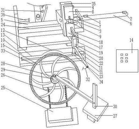
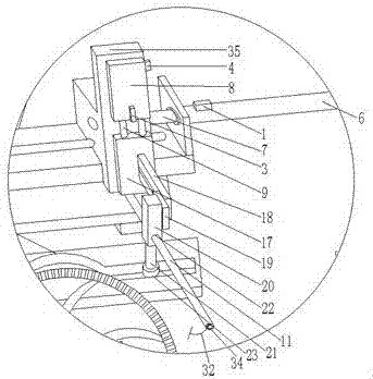
[0047] See figure 1 In this embodiment, the left and right transmission mechanism is the first cylinder 6, the upper and lower transmission mechanism is the second cylinder 8. Both ends of the base 5 are provided with vertical ears (not shown in the figure), and the vertical ears are provided with connecting holes (not marked in the figure). Out), the first cylinder 6 is horizontally arranged in the connecting hole, the second cylinder 8 is vertically arranged at the end of the first piston rod 7 of the first cylinder 6; the first cylinder 6 is provided with a first sensor 1, the first A second sensor 2 is provided at the end of the cylinder 6, a third sensor 3 is provided at the opening of the second cylinder 8, a fourth sensor 4 is provided at the end of the second cylinder 8, a first sensor 1, a second sensor 2, a third sensor 3 and The fourth sensors 4 are electrically connected to the control system 14; the second piston rod 9 of the second cylinder 8 is provided with an ou...

Embodiment 2

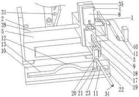
[0052] The working principle of the winding device of this embodiment is basically the same as that of the first embodiment, except that: figure 2 The left and right transmission mechanisms of this embodiment are the screw guide rail 39 and the second servo motor 40. The screw guide rail 39 and the second servo motor 40 are connected by a second toothed belt 41. The second servo motor 40 is connected to the control system 14 Electrical connection; the screw guide rail 39 is arranged on the base 5, the first slider 35 and the screw guide rail 39 are connected in a transmission type for connecting the second cylinder 8; the second sensor 2 moves left and right relative to the screw guide 39, the first sensor 1 is installed at one end of the screw guide 39. In the dual-cylinder structure, the movement force of the piston rod is fixed, and in practical applications, the stopper 36 is needed to limit the extension length of the piston rod, and the outlet pipe 11 is passively stopped...


PUM


Abstract

The invention discloses winding equipment and method for a lampblack separator network disc. The winding equipment comprises a conveying structure, a winding motion structure and a control system. The winding motion structure comprises a base, a left-right transmission mechanism, an up-down transmission mechanism and an arc-shaped sliding groove. The left-right transmission mechanism is horizontally arranged at the end of the base. The up-down transmission mechanism is perpendicular to the left-right transmission mechanism. The winding equipment further comprises a sensing system for being in linkage with the left-right transmission mechanism and the up-down transmission mechanism. The sensing system is electrically connected with the control system. By the adoption of the winding equipment, the structure linkage is achieved through the cooperation of the double-way transmission mechanisms and multiple sensors, the hand-made manufacturing method is simulated, the working efficiency of winding of the surface of the network disc is improved remarkably, and the labor is saved.

Description

Technical field [0001] The invention relates to the field of equipment processing and manufacturing, and in particular to a winding equipment and a winding method of a fume separator net plate. Background technique [0002] For the description of the net plate structure of the oil fume separator in the range hood in the prior art: the net plate is a disc shape, and the center of the two sides of the net plate protrudes from the surface of the net plate. Densely equiangularly set up the wire grooves. The wire grooves are used for double-sided winding metal wires or steel wires on the surface of the net disk. At present, the method of winding in the wire grooves is only manual operation, and the metal wires need to be manually aligned with the thin wires. The grooves are wound tightly in multiple turns, so that at least one metal wire is wound on the surface of each groove. This process is slow and winding hard materials is also harmful to human hands. [0003] Therefore, a new tech...

Claims


Application Information

Patent Timeline
Patent Type & Authority Applications(China)
IPC IPC(8): B21C47/04B21C47/34
CPCB21C47/04B21C47/34
Inventor 余永东
Owner 中山市逸博科技有限公司
Why Eureka
Try Eureka