A short-stress rolling mill turning device
A technology of short stress rolling mill and turning device, applied in the direction of metal rolling stand, metal rolling mill stand, metal rolling, etc., to achieve the effect of reduced requirements, small size and optimized structure
- Summary
- Abstract
- Description
- Claims
- Application Information
AI Technical Summary
Problems solved by technology
Method used
Image
Examples
Embodiment 1
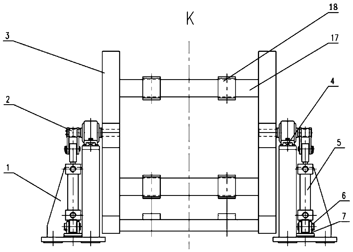
[0037] like figure 1 , figure 2 As shown, a short-stress rolling mill turnover device in this embodiment includes a fixed base 1, a transmission mechanism 2 and a turnover platform 3, wherein the fixed base 1 is symmetrically arranged on both sides of the turnover platform 3, and the Bolts are fixed on the civil foundation; the transmission mechanism 2 is symmetrically installed on the fixed base 1, and is fixedly connected with the turning platform 3, and the turning platform 3 is driven by the transmission mechanism 2 to turn over.
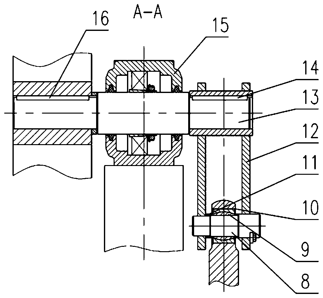
[0038] combine figure 2 , image 3 The transmission mechanism 2 of this embodiment includes a hydraulic cylinder 5, a hydraulic cylinder base 7, a connecting rod 12, a transmission shaft 13 and a bearing seat 15, wherein the hydraulic cylinder base 7 is installed on the fixed base 1 by bolts, and the The hydraulic cylinder 5 is the tail earring type, and is connected with the hydraulic cylinder base 7 through the pin shaft I6. One end of the...
Embodiment 2
[0043] A kind of short-stress rolling mill turnover device of this embodiment, its structure is basically the same as embodiment 1, and its difference is: as Figure 6 , Figure 7 As shown, in the present embodiment, two crossbeams 17 are connected between the horizontal right angle sides and the vertical right angle sides of the two triangular frames, wherein one crossbeam 17 is located at the junction center of the triangle frame right angle side and the hypotenuse, and the other A crossbeam 17 is located at one end close to the junction of two right-angled sides of the triangular frame, and each crossbeam 17 is correspondingly provided with two groups of pads: the third pad group 24 and the fourth pad group 25, and the spacing between the two groups of pads is different Specifically, in this embodiment, the distance between the third spacer group 24 is relatively large, and a larger rolling mill can be placed, and the distance between the fourth spacer group 25 is relativel...
Embodiment 3
[0047] A kind of short-stress rolling mill turnover device of this embodiment, its structure is basically the same as embodiment 1, and its difference is: as Figure 4 , Figure 5 As shown, the turning platform 3 of the present embodiment is horizontally provided with six crossbeams, and three crossbeams are respectively connected between the horizontal right-angled sides and the vertical right-angled sides of the two triangular frames, wherein, the first crossbeam 19 and the third crossbeam 21 There is a corresponding first pad set 22 on it, which is used to place a relatively large rolling mill. The second beam 20 and the third beam 21 are provided with a corresponding second pad set 23, which is used to place a relatively small rolling mill. rolling mill. Above-mentioned first crossbeam 19 is positioned at the intersection center of the right-angled side and the hypotenuse of triangular frame, and the third crossbeam 21 is positioned at an end close to the junction of two ...
PUM
 Abstract
Description
Claims
Application Information
 - R&D
- Intellectual Property
- Life Sciences
- Materials
- Tech Scout
- Unparalleled Data Quality
- Higher Quality Content
- 60% Fewer Hallucinations
Browse by: Latest US Patents, China's latest patents, Technical Efficacy Thesaurus, Application Domain, Technology Topic, Popular Technical Reports.
© 2025 PatSnap. All rights reserved.Legal|Privacy policy|Modern Slavery Act Transparency Statement|Sitemap|About US| Contact US: help@patsnap.com


