Vacuum decompression drying equipment

A drying equipment, vacuum decompression technology, applied in the direction of instruments, coatings, pretreatment surfaces, etc., can solve the problem of uneven color, reduce uneven air distribution, prevent uneven color, and improve uneven color. Effect

Active Publication Date: 2021-01-29
WUHAN CHINA STAR OPTOELECTRONICS TECH CO LTD
View PDF12 Cites 0 Cited by
  • Summary
  • Abstract
  • Description
  • Claims
  • Application Information

AI Technical Summary

Problems solved by technology

[0004] The invention provides a vacuum decompression drying equipment, which is used to solve the technical problem of uneven color caused by the accumulation of photoresist and solvent vapor on the substrate in the decompression drying process in the prior art

Method used


Image

  • Vacuum decompression drying equipment
  • Vacuum decompression drying equipment
  • Vacuum decompression drying equipment

Examples


Embodiment Construction

[0034]The present invention will be further described below in conjunction with the drawings.

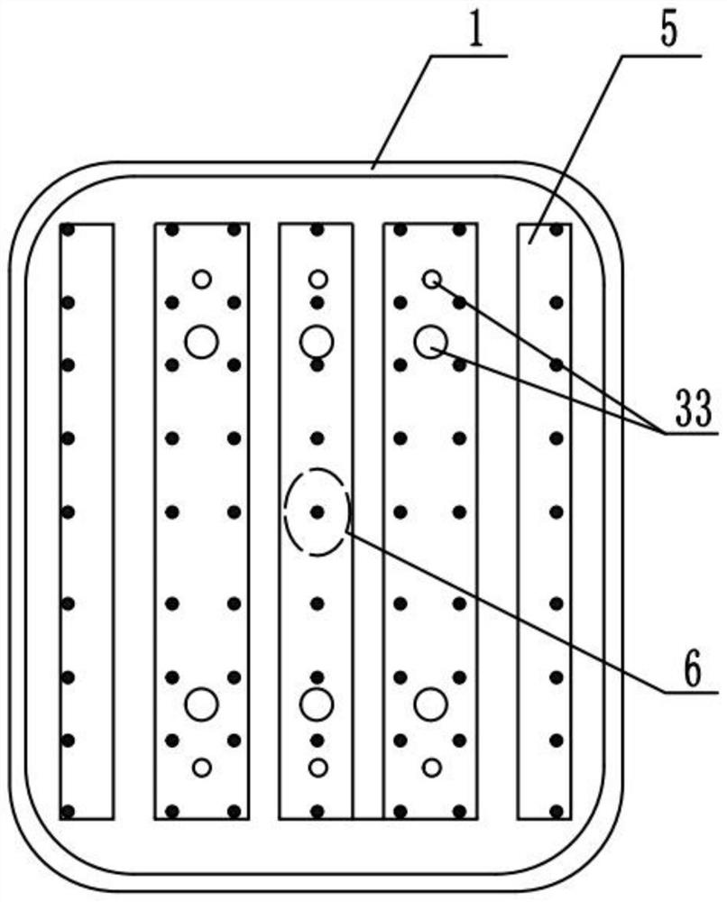
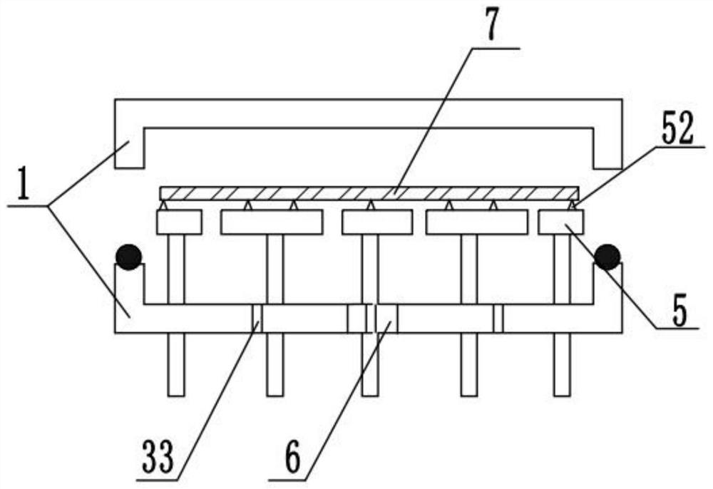
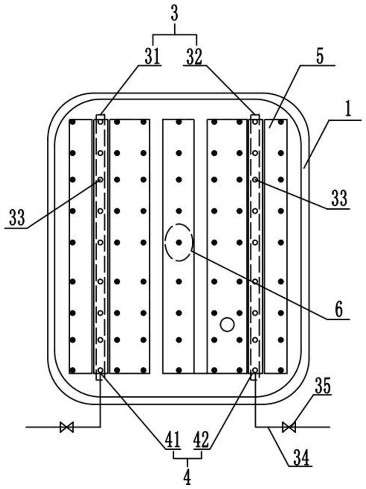
[0035]Such asimage 3 As shown, the present invention provides a vacuum decompression drying equipment, which includes: a cover plate 1 and a chamber 2 inside the cover plate 1, a substrate is arranged in the chamber 2; The vacuum device 3; the vacuum breaking device 3 includes at least a first blowing hole array 31 and a second blowing hole array 32, the first blowing hole array 31 and the second blowing hole array 32 both include multiple holes arranged along the long side of the cover plate 1. A blow hole 33. The blowing hole 33 is used to pass dry air (CDA) into the chamber 2 to restore the air pressure in the chamber 2.

[0036]Such asimage 3 As shown, the first row of blowing holes array 31 is close to the side wall of the cover plate 1 in the longitudinal direction, and the second row of blowing holes 32 is close to the other side wall of the cover plate 1 in the long direction.

[0037]In o...


PUM


Abstract

The invention discloses a vacuum decompression drying equipment, which relates to the manufacturing field of thin-film transistor liquid crystal displays, and is used to solve the problem of discoloration caused by the aggregation of photoresist and solvent vapor on the substrate in the middle region of the substrate in the decompression drying process existing in the prior art. Technical problems of inhomogeneity. The vacuum decompression drying equipment of the present invention comprises a cover plate and a chamber, and the first blowing hole array and the second blowing hole array on the cover plate all include blowing holes distributed along the long side direction of the cover plate, so in the vacuum breaking process Among them, the airflow distribution inside the entire chamber is more uniform, and the position of the air blowing hole is shorter from the central area of ​​the substrate, which is more likely to affect the airflow in the central area and prevent the uneven color of the substrate caused by the condensation of solvent vapor.

Description

Technical field[0001]The invention relates to the manufacturing field of thin film transistor liquid crystal displays, and in particular to a vacuum decompression drying equipment.Background technique[0002]Existing vacuum decompression drying equipment (VCD) such asfigure 1 withfigure 2 As shown, when the substrate is placed on the pin of the vacuum decompression drying equipment by the robot, the vacuum decompression drying equipment starts the process, and the dry air (CDA) is introduced into the cover after the process is over To restore the air pressure in the chamber.[0003]Since the photoresist is composed of solvents, photosensitizers, resins, and additives, the solvent accounts for more than 75% of all components. After the substrate is coated with photoresist, the photoresist film layer on the substrate has greater fluidity. Even after the vacuum drying process of the vacuum vacuum drying equipment, there are still more solvents in the photoresist and a certain flow ability....

Claims


Application Information

Patent Timeline
Patent Type & Authority Patents(China)
IPC IPC(8): B05D3/04G02F1/13
CPCB05D3/042B05D3/0493G02F1/1303
Inventor 郭开超
Owner WUHAN CHINA STAR OPTOELECTRONICS TECH CO LTD
Why Eureka
Try Eureka