Rotary nozzles for high-pressure cleaning equipment

一种旋转喷嘴、高压清洁的技术,应用在具有活动出口的喷洒装置、喷射装置等方向,能够解决降低流体束清洁效果、流体束散开等问题,达到造型容易、低成本、低制造的效果

Active Publication Date: 2019-09-20
ALFRED KARCHER GMBH & CO KG
View PDF4 Cites 0 Cited by
  • Summary
  • Abstract
  • Description
  • Claims
  • Application Information

AI Technical Summary

Problems solved by technology

[0004] If the nozzle body has a very high speed of rotation about the longitudinal axis of the housing, then it can have the result that the fluid jet escaping from the outlet is scattered and thus the cleaning effect of the fluid jet hitting the surface is reduced.

Method used


Image

  • Rotary nozzles for high-pressure cleaning equipment
  • Rotary nozzles for high-pressure cleaning equipment
  • Rotary nozzles for high-pressure cleaning equipment

Examples


Embodiment Construction

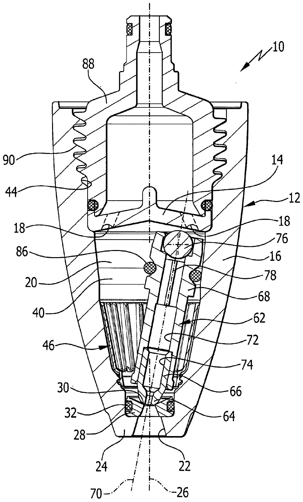
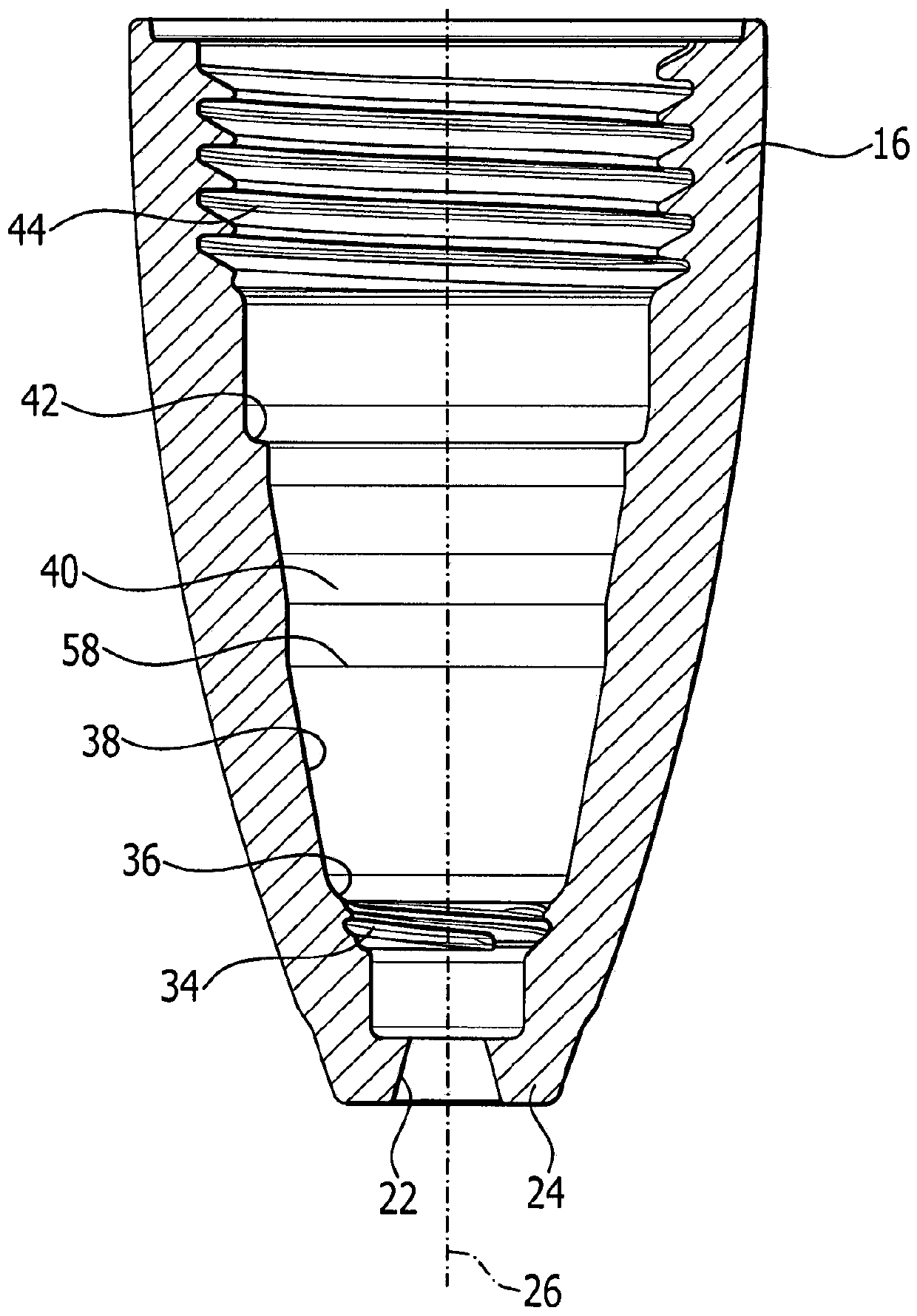
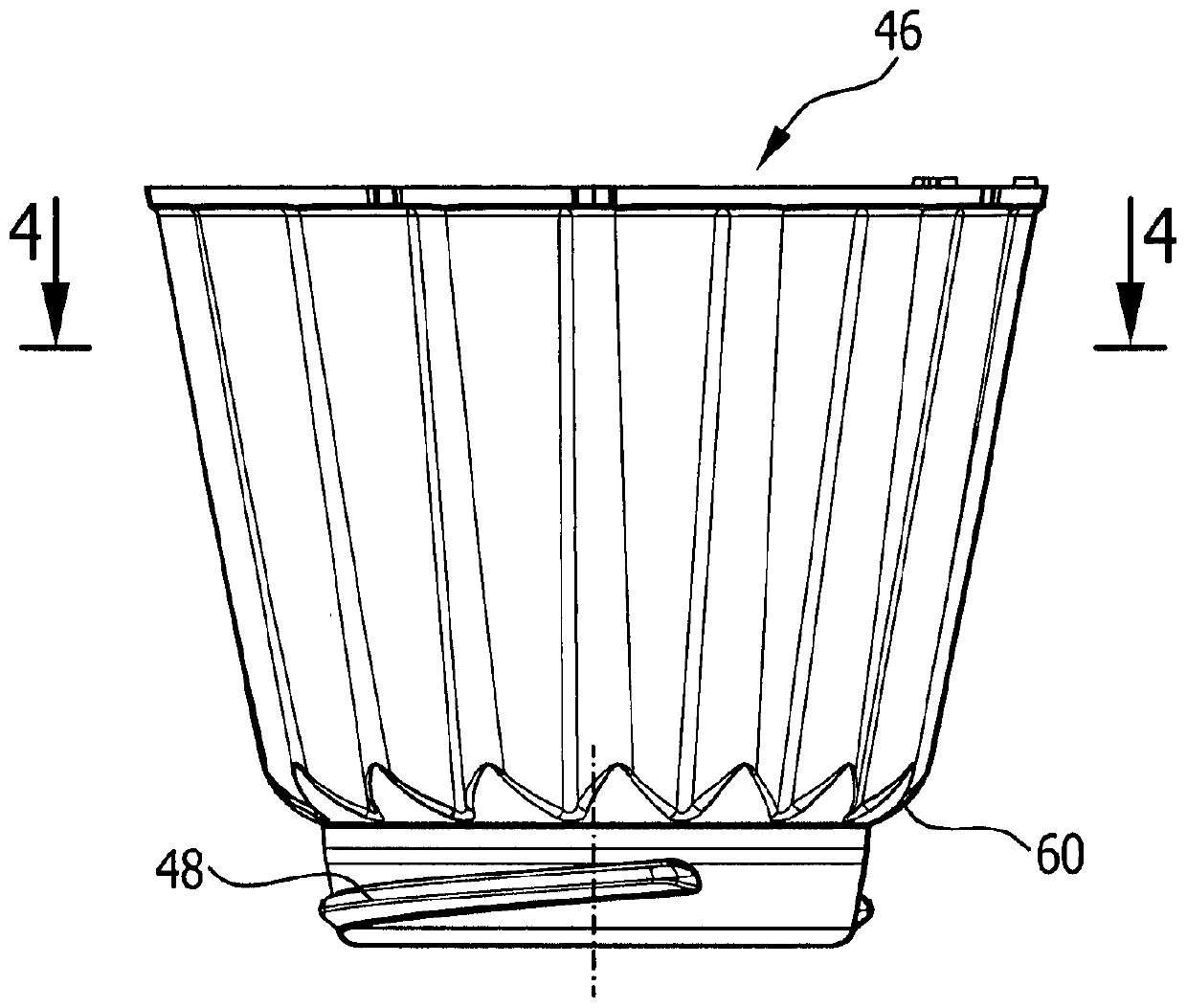
[0038] exist Figures 1 to 4 A first advantageous embodiment of the rotary nozzle according to the invention is schematically shown in FIG. 1 , which is designated as a whole by the reference numeral 10 . The rotary nozzle 10 has a housing 12 with a housing bottom 14 and a housing cover 16 . The housing bottom 14 is designed in the shape of a plate and has a plurality of tangential openings 18 , which open into the interior 20 of the housing 12 . The inner chamber 20 is surrounded by the housing cover 16 and narrows from a tangential inlet 18 to an outlet 22 arranged on an end wall 24 of the housing cover 16 .

[0039] Via the tangential inlet 18 , a fluid under pressure can be supplied to the inner chamber 20 , which rotates in the inner chamber 20 about the housing longitudinal axis 26 and can escape from the housing 12 via the outlet 22 .

[0040] Arranged in the inner chamber 20 immediately upstream of the outlet opening 22 is a bearing in the form of a bearing ring 28 w...


PUM


Abstract

A rotary nozzle (10) for a high-pressure cleaning device is provided, which has a housing (12) with at least one inlet opening (18) tangentially and an end wall (24) arranged on the An outlet (22) on which a central pan-shaped recess (30) is arranged, the rotating nozzle also having a nozzle body arranged in the housing (12) and having a through channel (72) and Supported with a spherical end (64) in a pan-shaped recess (30), the longitudinal axis (70) of the nozzle body is inclined relative to the longitudinal axis (26) of the housing (12) and through which the flow is directed. The fluid of the body (12) is placed in a circular motion, wherein the nozzle body is supported on a support surface (40), wherein a plurality of chokes are arranged downstream of the support surface (40) on the wall of the housing (12) Components, each of which has a baffle surface (52; 120). In order to effectively limit the rotation speed of the nozzle body (62) without significantly damaging the starting performance of the nozzle body (62), guide surfaces (54; 122) are placed on each deflection surface (52) relative to the flow direction of the fluid. ; 120) In front, the baffle surface (52; 120) is continuously connected to the guide surface, wherein the guide surface (54; 122) is oriented obliquely to the radial plane of the housing (12).

Description

technical field [0001] The invention relates to a rotary nozzle for a high-pressure cleaning device, the rotary nozzle has a housing with at least one inlet opening tangentially into the housing and an outlet arranged on the end wall of the housing, at which outlet Arranged with a bearing having a central through-pan-shaped depression, the rotary nozzle also has a nozzle body, which is arranged in the housing, has a through-channel and is supported with a spherical end in the pan-shaped depression, the longitudinal axis of the nozzle body Inclined with respect to the longitudinal axis of the housing and set in an orbital movement by the fluid flowing through the housing, wherein the longitudinal axis of the nozzle body runs around on a conical surface and the nozzle body is supported with its circumferential contact surface on the support On the surface, wherein, downstream of the support surface on the wall of the housing, a plurality of flow blocking elements are arranged at...

Claims


Application Information

Patent Timeline
Patent Type & Authority Patents(China)
IPC IPC(8): B05B3/04
CPCB05B3/0463B08B3/026B05B3/0418B05B1/02
Inventor 斯文·迪恩贝格尔比约恩·施瓦茨斯特凡·维尔纳约翰·乔治·韦舍
Owner ALFRED KARCHER GMBH & CO KG
Why Eureka
Try Eureka