Mixing device for desulfurization of flue gas generated by thermal power generation

A thermal power generation and mixing device technology, which is applied to mixers, mixers with rotating stirring devices, gas treatment, etc., can solve the problems of polluting the environment, increasing the failure rate of stirring devices, and accelerating the use loss of stirring devices, so as to reduce damage degree, smooth operation, and the effect of avoiding hard collisions

Inactive Publication Date: 2017-11-28
绵阳行之智汇知识产权服务有限公司
View PDF2 Cites 0 Cited by
  • Summary
  • Abstract
  • Description
  • Claims
  • Application Information

AI Technical Summary

Problems solved by technology

However, after coal combustion in the boiler, a large amount of flue gas will be produced. The flue gas contains a large amount of harmful substances, and the direct release will seriously pollute the environment. The traditional flue gas purification treatment usually uses a desulfurization tower to desulfurize the flue gas. treatment to reduce the release of harmful substances, but the slurry at the bottom of the existing desulfurization tower contains a large number of solid particles, mainly fly ash and desulfurization medium particles, the particle size is generally 0-400µ; m, more than 90% are 20-60µ m, the concentration is 5%~28% (mass ratio), these solid particles (especially Al2O3, SiO2 particles) have very strong abrasiveness, and when the slurry at the bottom of the desulfurization tower is stirred, conventional stirring blades It is easy to be impacted by the solid phase in the slurry, causing the stirring blade to swing radially, and the resulting stress will be transmitted to the final power output end through the torque, which will increase the failure rate of the stirring device and accelerate the wear and tear of the stirring device.

Method used


Image

  • Mixing device for desulfurization of flue gas generated by thermal power generation

Examples


Embodiment 1

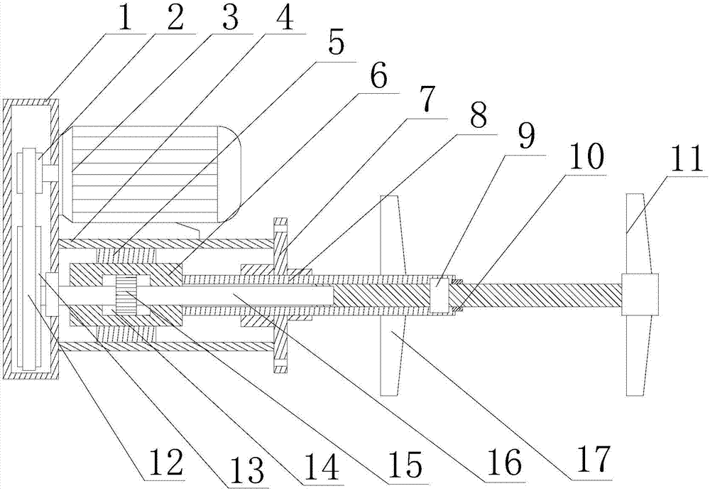
[0021] Such as figure 1 As shown, this embodiment includes a box body 1, a motor 3 and a fixed cylinder 4 arranged on the side wall of the box body 1, the motor 3 is arranged on the fixed cylinder 4, and the output end of the motor 3 runs through the side wall of the box body 1 Then continue to extend, the driving wheel 2 is installed on the extension section of the output end of the motor 3, and the end of the fixed cylinder 4 away from the box body 1 is equipped with a flange 7, and also includes a linkage shaft 16 arranged in the fixed cylinder 4 And the bearing 5 arranged on the inner peripheral wall of the fixed cylinder 4, the sleeve 8 is sleeved on the outer peripheral wall of the linkage shaft 16, the inner peripheral wall of the bearing 5 is in contact with the outer peripheral wall of the sleeve 8, One end of the sleeve 8 extends outwards after penetrating the flange 7, and an auxiliary vane 17 is fixed on the outer peripheral wall of the extension section of the sle...


PUM


Abstract

The invention discloses a mixing device for desulfurization of flue gas generated by thermal power generation. The mixing device comprises a tank body, a motor and a fixing cylinder, wherein the motor is arranged on the fixing cylinder; a driving wheel is mounted on the extension section of the output end of the motor; the outer circumferential wall of a linking shaft is sleeved by a sleeve; one end of the sleeve penetrates through a flange disc and extends outwards; secondary blades are fixed on the outer circumferential wall of the extension section of the sleeve; the other end of the sleeve is arranged inside the fixing cylinder; a linking column is connected with one end of the sleeve; a cavity is formed inside the linking column; an inner tooth belt is arranged on the inner circumferential wall of the cavity; a gear is arranged on the linking shaft; one end of the linking shaft sequentially penetrates through the cavity and the rear wall of the tank body and extends continuously; a driven wheel is mounted on the extension section of the linking shaft; and main blades are mounted at the tail end of the linking shaft. Aiming at the problem that a conventional stirring blade is seriously damaged, the inventor designs a slurry stirring and mixing procedure which is applicable to relatively large solid-phase granules, namely, on premise that stable operation of stirring blades is ensured, the slurry stirring efficiency is improved.

Description

technical field [0001] The invention relates to the field of thermal electric field power generation, in particular to a mixing device for flue gas desulfurization of thermal power generation. Background technique [0002] The thermal power plant uses coal as fuel, and the coal is burned in the boiler to heat the water in the boiler to generate steam, and then the steam with a certain temperature and pressure from the boiler enters the steam turbine through the main steam valve and the regulating steam valve, and flows through the steam turbine in turn. A series of ring-mounted nozzle cascades and moving blade cascades expand and do work, convert their heat energy into mechanical energy that drives the turbine rotor to rotate, and drive the generator to generate electricity through the coupling. The steam after expansion and work is discharged from the steam exhaust part of the steam turbine. When the condenser is condensed into water, it is sent to the heater, and then sent...

Claims


Application Information

Patent Timeline
Patent Type & Authority Applications(China)
IPC IPC(8): B01F7/04B01F15/00B01D53/80B01D53/48
CPCB01D53/48B01D53/80B01D2258/0283B01F27/213B01F27/70B01F2035/353B01F35/10
Inventor 王伟
Owner 绵阳行之智汇知识产权服务有限公司
Why Eureka
Try Eureka