


Quick Research
Generate reliable direction feasibility study reports for your R&D in just a few steps.

Technical Q&A
Discover and master advanced knowledge NOW. Basics, ideas, possibilities, all at once.

Find Solutions
As an expert in R&D theories, this can generate solutions to your technical problems instantly.

Evaluate Feasibility
Analyze your overall solution with one click, know your potential R&D risks in advance.

Monitor Landscape
Get weekly tech updates, stay abreast of the latest tech innovations and key insights.
Modular battery equalization circuit based on push-pull converter and control method of modular battery equalization circuit
A technology for modularizing batteries and balancing circuits, applied in charge balancing circuits, battery circuit devices, circuit devices, etc., can solve the problems of long balancing paths, complicated control, and poor scalability, and achieve simple control, eliminate cross effects, and ensure balance. Effect
- Summary
- Abstract
- Description
- Claims
- Application Information
AI Technical Summary
Problems solved by technology
Method used
Image

Examples
Embodiment 1
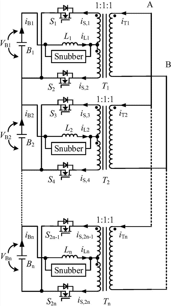
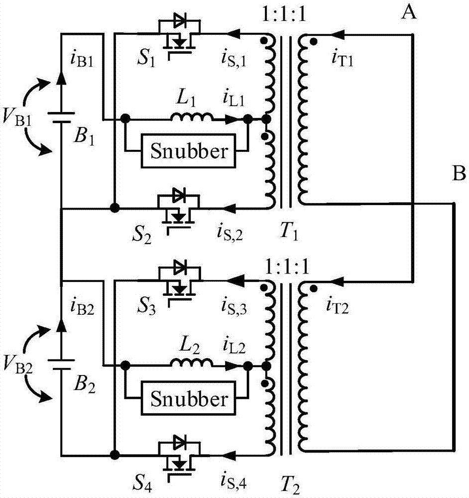
[0038] Taking dual output as an example, the structure is as follows figure 2 As shown, when the input voltage is higher than the bus voltage, the circuit has four modes, as shown in Fig. 3(a), Fig. 3(b), Fig. 3(c), and Fig. 3(d) respectively. The working mode circuit diagram when the voltage is higher than the bus voltage, at this time the excitation inductance is large, V B1 >V B2 .
[0039] The circuit has four modes when the input voltage is higher than the bus voltage.
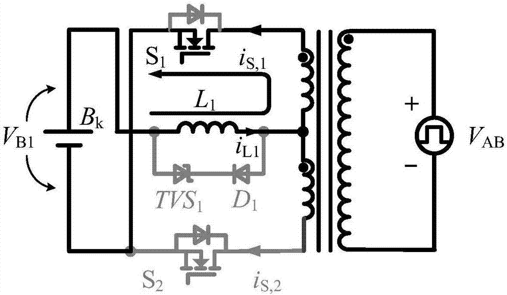
[0040] Mode1: The mode-to-mode correspondence in Figure 3(a) Figure 4 middle t 1 time period, at this time the upper switch tube S 1 conduction, the lower switching tube S 2 closure. The voltage on the AC bus AB is the average of the two input battery voltages - (V 1 +V 2 ) / 2, the current flows from the AC bus through the inductance into the terminal with the same name on the secondary side of the transformer, the current i L Positive increase. During this period, battery B 1 Discharge throu...
Embodiment 2
[0046] Taking dual output as an example, the structure is as follows figure 2 As shown, when the input voltage is lower than the bus voltage, the circuit has four modes, as shown in Fig. 5(a), Fig. 5(b), Fig. 5(c), and Fig. 5(d). The working mode circuit diagram when the voltage is lower than the bus voltage, at this time the excitation inductance is large, V B1 >V B2 .
[0047] Mode1: The mode-to-mode correspondence in Figure 5(a) Image 6 middle t 1 time period, at this time the upper switch tube S 3 conduction, the lower switching tube S 2j off, the voltage on the AC bus is the average of the two input voltages - (V 1 +V 2 ) / 2, leakage inductance current i L Positive increase, flow through the switching tube S 2j-1 The current is equal to the current flowing through the inductor L. battery B 2 Power is drawn from other batteries via an AC parallel bus. When the switch tube S 3 When closed, the modal one ends.
[0048] Mode2: Mode 2 in Figure 5(b) corresponds ...
Embodiment 3
[0055] Figure 8 It is the circuit topology diagram of the present invention taking three-way output as an embodiment, Figure 9 for Figure 8 The simulation waveform of the embodiment, its simulation parameters are: the first road input branch battery voltage V 1 =3.7V, the second input branch voltage V 2 =3.2V The third input branch voltage V 3 = 3.4V, L 1 =L 2 =L 3 =5uΩ. from Figure 9 It can be seen that this circuit can realize the function of automatic equalization.
PUM
 Abstract
Description
Claims
Application Information
 - R&D Engineer
- R&D Manager
- IP Professional
- Industry Leading Data Capabilities
- Powerful AI technology
- Patent DNA Extraction
Browse by: Latest US Patents, China's latest patents, Technical Efficacy Thesaurus, Application Domain, Technology Topic, Popular Technical Reports.
© 2024 PatSnap. All rights reserved.Legal|Privacy policy|Modern Slavery Act Transparency Statement|Sitemap|About US| Contact US: help@patsnap.com