
Indoor unit and controlling method thereof

A technology for indoor units and cabinets, applied in airflow control components, heating and ventilation control systems, heating methods, etc., can solve problems such as condensation on the outer surface of the air outlet, affect user experience, and limited anti-condensation effect, and achieve Simplify the production process, prevent condensation, and choose flexible effects

Active Publication Date: 2017-11-24
QINGDAO HAIER AIR CONDITIONER GENERAL CORP LTD
View PDF6 Cites 3 Cited by
  • Summary
  • Abstract
  • Description
  • Claims
  • Application Information

AI Technical Summary

Problems solved by technology

[0002] When the air conditioner is used in a high-humidity environment, condensation will appear on the outer surface of the air outlet, which will affect the user experience
The existing anti-condensation solutions mainly use thermal insulation materials for heat insulation, the production process is complex, and the cost is high, and the anti-condensation effect is limited

Method used


Image

  • Indoor unit and controlling method thereof
  • Indoor unit and controlling method thereof
  • Indoor unit and controlling method thereof

Examples


Embodiment Construction

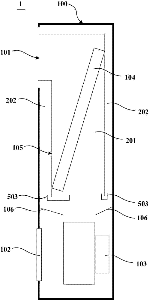
[0038] figure 1 It is a schematic side sectional view of the indoor unit 1 of the cabinet air conditioner according to one embodiment of the present invention. The indoor unit 1 may generally include a casing 100 and a fan 103 , a heat exchanger 104 and an air duct assembly disposed therein. The casing 100 may have an air inlet 102 at its lower portion and an air outlet 101 at its upper portion. There may be one air inlet 102 and one air outlet 101 , and they are located at the lower part and the upper part of the front panel of the casing 100 . The air inlet 102 and the air outlet 101 can also be multiple, and the multiple air outlets 101 can also be located at the back and / or side of the casing 100, and the multiple air inlets 102 can also be located on the front panel and the side wall of the casing. lower part.

[0039] The blower 103 can be disposed inside the casing 100 and located inside the air inlet 102 (rear side or left / right side), so as to accelerate the air en...


PUM


Abstract

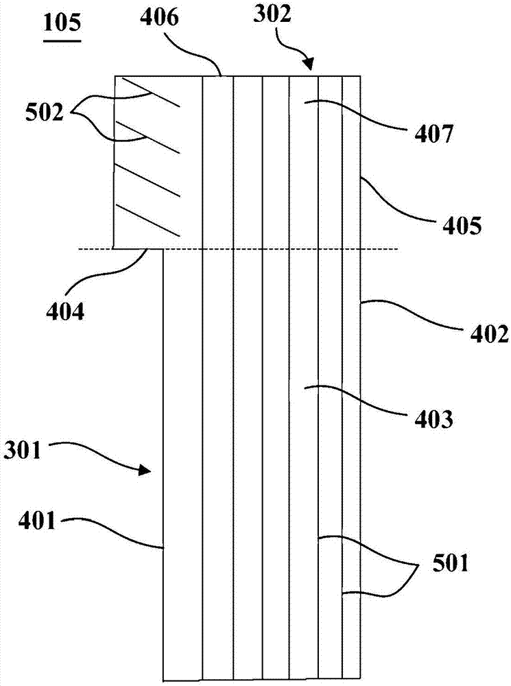
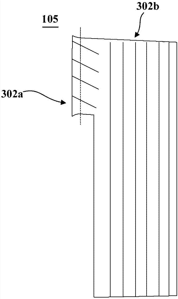
The invention provides an indoor unit of a cabinet air conditioner. The indoor unit comprises a machine shell, a draught fan, a heat exchanger and an air duct assembly, wherein an air inlet and an air outlet are formed in the machine shell; the draught fan is arranged in the machine shell and located on the inner side of the air inlet, and air which enters the machine shell from the air inlet is urged to be accelerated to flow towards the air outlet; the heat exchanger is arranged in the machine shell and located at a flowing path from the draught fan to the air outlet, and heat exchanging is conducted on the air flowing through the heat exchanger; the air duct assembly is arranged in the machine shell; the air duct assembly is assembled to guide the part of air blown out of the draught fan to the heat exchanger, heat exchanging is conducted on the air and the heat exchanger to form temperature-changed heat exchanging air flow, and the heat exchanging air flow is guided to pass through a first air outlet position of the air outlet and flow out of the machine shell; the other part of air blown out of the draught fan is isolated from the heat exchanger to form isolated air flow which does not conduct heat exchanging with the heat exchanger, and the isolated air flow is guided to pass through a second air outlet position located on the circumferential side of the first air outlet and flow out of the machine shell; and the first air outlet position is separated from the machine shell through the second air outlet position.

Description

technical field [0001] The invention relates to an air conditioning device, in particular to an indoor unit of a cabinet air conditioner. Background technique [0002] When the air conditioner is used in a high-humidity environment, condensation will appear on the outer surface of the air outlet, which will affect the user experience. The existing anti-condensation solutions mainly use thermal insulation materials to insulate the heat, the production process is complex, and the cost is high, and the anti-condensation effect is limited. Contents of the invention [0003] An object of the present invention is to provide an indoor unit of a cabinet air conditioner capable of preventing condensation. [0004] A further object of the present invention is to simplify the manufacturing process and reduce the manufacturing cost of the indoor unit. [0005] Another further object of the present invention is to provide a control method for controlling the formation of an isolated ...

Claims


Application Information

Patent Timeline
Patent Type & Authority Applications(China)
IPC IPC(8): F24F1/00F24F13/30F24F13/02F24F13/08F24F13/22F24F11/00
CPCF24F1/0007F24F1/0059F24F13/02F24F13/08F24F13/22F24F13/30F24F2013/221
Inventor 刘超超曾福祥王彦生董积菊
Owner QINGDAO HAIER AIR CONDITIONER GENERAL CORP LTD
Learn More