
Sliding combination door

A technology of combining doors and door bodies, applied in the direction of windows/doors, door/window accessories, building components, etc., can solve the problems of complex structure of electric drive system, inconsistent speed of left and right roller shutters, easy corrosion and aging of structural parts, etc. The effect of derailment or stuck, saving power consumption and low maintenance cost

Active Publication Date: 2017-11-24
徐扬
View PDF5 Cites 3 Cited by
  • Summary
  • Abstract
  • Description
  • Claims
  • Application Information

AI Technical Summary

Problems solved by technology

[0002] At present, rolling shutter doors are mostly used in workshops or warehouses, and the speed of the left and right rolling shutters is inconsistent, which can easily cause the rolling shutters to be detached or stuck. At the same time, the service life of the rolling shutters is short and the maintenance cost is high, especially for wide workshops.
There are also those who use sliding doors at present. When using sliding doors, the lower load-bearing wheels are often used. The friction resistance is large, the structure of the electric drive system is complicated, and the sealing performance is poor. , The upper track of the sliding door is made of I-beam, which is easy to cause derailment, and the airtightness is poor, and the structural parts are easy to rust and age

Method used


Image

  • Sliding combination door
  • Sliding combination door
  • Sliding combination door

Examples


Embodiment Construction

[0024] The present invention will be further described below in conjunction with accompanying drawing by non-limiting embodiment:

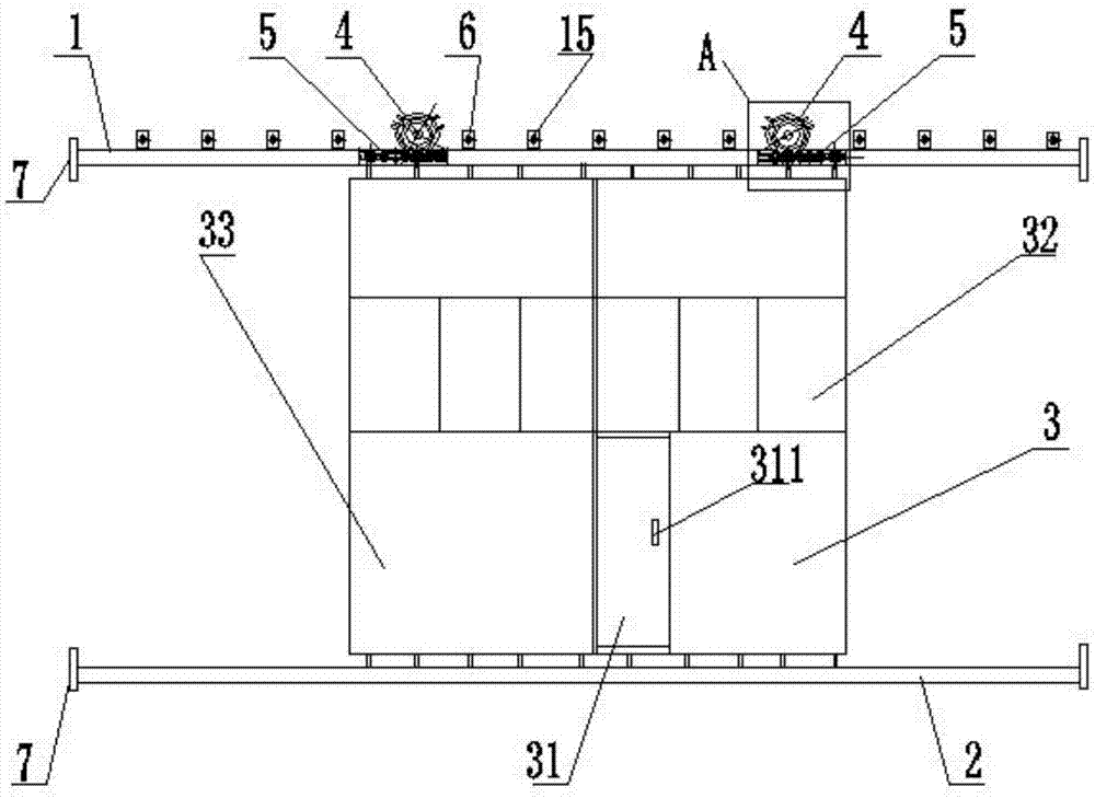
[0025] As shown in the drawings, a push-pull combination door includes two door bodies 3 arranged side by side, an upper guide rail 1, a lower guide rail 2, and two door body transmission mechanisms.

[0026] The door body 3 is a frame structure, the door surface of the door body 3 is inlaid with anti-static material or corrugated board, adopts the buckle bite mode, the door body 3 is provided with a small door 31, and the small door 31 is connected with the door body frame Adopt hinge connection, be provided with wicket 311 on wicket 31. A viewing window 32 is arranged at a suitable position of the door body. Around the inner side of the door body 3 is provided with a sealing rubber strip 34, which can be bonded to seal and prevent dust.

[0027] The upper guide rail 1 and the lower guide rail 2 are arranged in parallel on the upper and lower s...

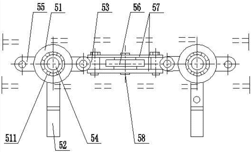
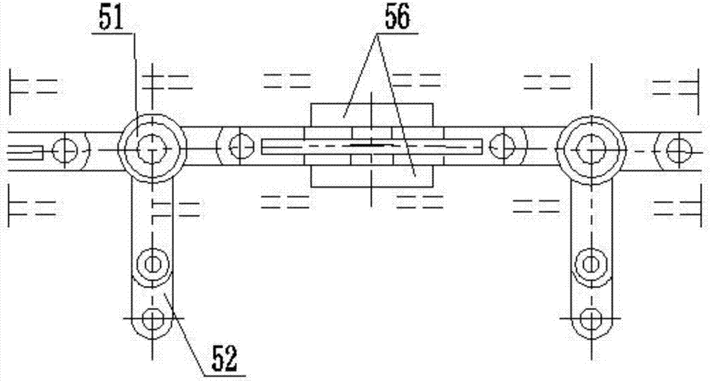

PUM


Abstract

The invention discloses a sliding combination door. The sliding combination door comprises a door body, an upper guide rail, a lower guide rail and a door body transmission mechanism; the upper guide rail and the lower guide rail are arranged in parallel and are of rectangular pipe structures; the door body transmission mechanism comprises a driving device and moving mechanisms which are arranged in the upper guide rail and the lower guide rail; a chain wheel is arranged on the output shaft of the driving device; each moving mechanism comprises a plurality of moving units which are hinged together in proper sequence; each moving unit comprise a load-bearing wheel assembly and a guide wheel assembly, and a load-bearing wheel of each load-bearing wheel assembly is perpendicular to a guide wheel of each guide wheel assembly; the moving mechanism arranged in the upper guide rail is connected with the upper end of the door body, an opening type structure is arranged on the upper guide rail, and the chain wheel of the driving device is engaged with the moving mechanism at the part of the opening type structure in a transmission mode; and the moving mechanism arranged in the lower guide rail is perpendicularly connected with the lower end of the door body through a buffering mechanism. According to the sliding combination door, the structure is simple, friction resistance is small, opening and closing of the door body is light and convenient, running is smooth, derailment or sticking is prevented, and the service life is long.

Description

technical field [0001] The invention relates to a push-pull combination door, in particular to a push-pull combination door for workshops and warehouses. Background technique [0002] At present, rolling shutter doors are mostly used in workshops or warehouses, and the speed of the left and right rolling shutters is inconsistent, which can easily cause the rolling shutters to fall out of the groove or get stuck. At the same time, the rolling shutters have a short service life and high maintenance costs, especially for wide-width workshops. There are also those who use sliding doors at present. When using sliding doors, the lower load-bearing wheels are often used. The friction resistance is large, the structure of the electric drive system is complicated, and the sealing performance is poor. , The upper track of the sliding door is made of I-beam, which is easy to cause derailment, and the airtightness is poor, and the structural parts are easy to rust and age. Contents of...

Claims


Application Information

Patent Timeline
Patent Type & Authority Applications(China)
IPC IPC(8): E06B3/46E05D13/00E05F15/632E05F5/08
CPCE05D13/00E05F5/08E05F15/632E06B3/4636
Inventor 徐扬
Owner 徐扬
Learn More