Timing quantitative flushing equipment of toilet bowl

A technology for flushing water and toilets, which is applied in the field of electronic induction flushing equipment and can solve problems such as wasting water resources

Inactive Publication Date: 2017-11-24
王明中
View PDF0 Cites 1 Cited by
  • Summary
  • Abstract
  • Description
  • Claims
  • Application Information

AI Technical Summary

Problems solved by technology

[0003] In order to solve the problem of wasting water resources in existing toilet flushers, the invention provides a timing and quantitative flushing device for toilets, which is composed of a controller, an induction probe, an electromagnetic water valve, etc., and the induction probe of the device is installed on the toilet or The back end of the bedpan is used to sense the existence of the human body. The electromagnetic water valve is installed on the outlet pipe of the water tank to control the opening and closing of the flushing pipe. The controller is used to control the working procedures of the induction probe and the electromagnetic water valve. After the power supply, the controller is in the standby state. When the human body is close to the toilet or bedpan, the sensor probe detects the existence of the human body and the controller starts the timing program. In the first stage, when the human body leaves within 0 to 2 minutes of the timing program of the device, the device activates the electromagnetic water valve to flush out a quarter of the water inside the water tank, and if it leaves within 2 to 5 minutes, it flushes out half of the water in the water tank. One of the water volume, if you leave after 5 minutes, all the water in the water tank will be flushed out, so as to realize the timing and quantitative automatic flushing action, which greatly saves water resources

Method used


Image

  • Timing quantitative flushing equipment of toilet bowl
  • Timing quantitative flushing equipment of toilet bowl

Examples


Embodiment Construction

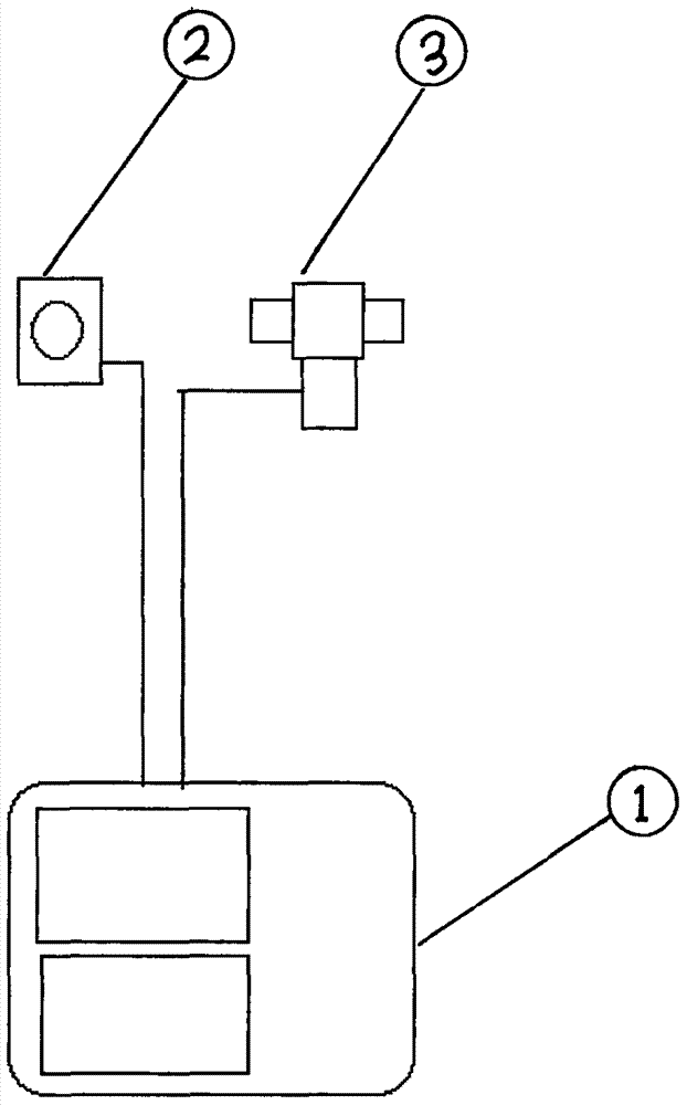
[0007] according to figure 1 It can be seen that the device is composed of a controller (1), an induction probe (2) and an electromagnetic water valve (3). The control circuit of the valve, the controller is powered by the mains power supply after the voltage transformation. When the power is turned on, the controller (1) is in the standby state, and the action command is controlled by the induction probe (2). When the induction probe (2) detects When the sensor (human body) detects the signal into the timing chip electric board and starts the timing program, when the sensor (human body) leaves the sensing probe (2), the timing program is terminated, and the timing chip electric board inputs the timing signal into the electromagnetic water valve. The control circuit is modulated by the control circuit of the electromagnetic water valve to generate a start-up power input to the electromagnetic water valve (3), thereby controlling the opening and closing of the electromagnetic w...


PUM


Abstract

The invention relates to toilet flushing equipment, especially an electronic induction flushing equipment. The timing and quantitative flushing equipment of the toilet is composed of a controller, an induction probe, an electromagnetic water valve, etc., and the induction probe of the equipment is installed in the toilet. Or the back end of the bedpan, used to sense the existence of the human body, the electromagnetic water valve is installed on the outlet pipe of the water tank, used to control the opening and closing of the water flow, the controller is used to control the working procedures of the induction probe and the electromagnetic water valve, and the device is powered on Then it is in standby mode. When the human body is close to the toilet or bedpan, the sensor probe detects the existence of the human body and the controller starts the timing program. The timing program has three stages: 0 to 2 minutes, 2 to 5 minutes, and full time. When the human body leaves within 0 to 2 minutes of the timing program of the equipment, the equipment will control the electromagnetic water valve to flush out the corresponding amount of water. water action.

Description

Technical field [0001] The invention relates to a toilet flushing device, in particular to an electronic induction flushing device. Background technique [0002] Existing flushing toilets are mechanical and electronic induction. Taking the electronic induction type as an example, the equipment will automatically flush after people use it. In many cases (such as when urinating), it does not need a large amount of water to flush. However, the amount of water flushed out by this device is the same or has only two grades, which greatly wastes precious water resources. Contents of the invention [0003] In order to solve the problem of wasting water resources in existing toilet flushers, the invention provides a timing and quantitative flushing device for toilets, which is composed of a controller, an induction probe, an electromagnetic water valve, etc., and the induction probe of the device is installed on the toilet or The back end of the bedpan is used to sense the existen...

Claims


Application Information

Patent Timeline
Patent Type & Authority Applications(China)
IPC IPC(8): E03D5/10
CPCE03D5/105
Inventor 王明中
Owner 王明中
Why Eureka
Try Eureka