
Pipeline dredging machine

A technology for dredging machines and pipelines, which is applied in the direction of cleaning hollow objects, cleaning methods and utensils, chemical instruments and methods, etc., which can solve the problems of inconvenient use and insufficient stability of performance, so as to ensure stable operation of equipment, good dredging performance, and good The effect of natural forward ability

Inactive Publication Date: 2017-11-24
RAILWAY ENG RES INST CHINA ACADEMY OF RAILWAY SCI +1
View PDF7 Cites 5 Cited by
  • Summary
  • Abstract
  • Description
  • Claims
  • Application Information

AI Technical Summary

Problems solved by technology

The existing pipe dredging machines on the market have shortcomings such as unstable performance and inconvenient use in tunnels.

Method used


Image

  • Pipeline dredging machine
  • Pipeline dredging machine
  • Pipeline dredging machine

Examples


Embodiment 1

[0051] Embodiment 1 nozzle structure design

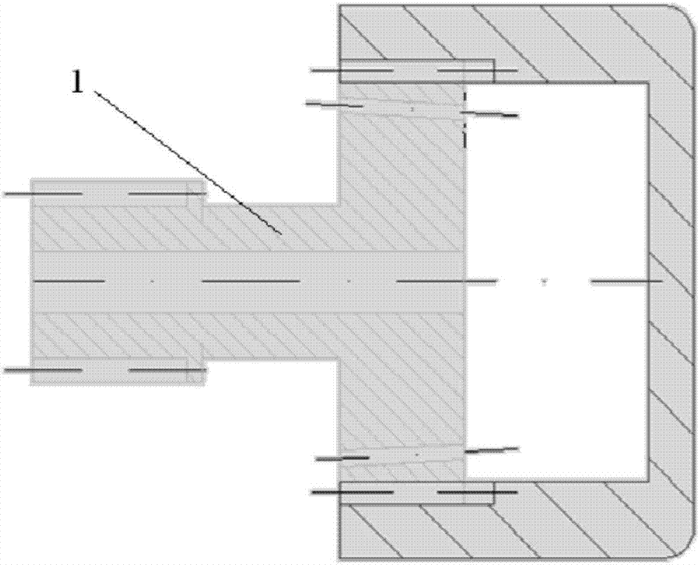
[0052] like figure 1 , the sprinkler head 1 has an integrated structure, and its appearance is cylindrical. The nozzle is mainly used to test the natural forward ability, and the nozzle is set at the rear of the nozzle, which is designed as 2 nozzles. Test with straight PVC pipe (see Figure 8 )

[0053] Test performance:

[0054] 1. Straight pipe passing capacity: the time to pass through a standard PVC straight pipe (length 4m) is 1 second.

[0055] 2. Bend pipe passing capacity: no less than two 90° elbows can be passed.

[0056] Problems: Because the cylindrical shape of the nozzle has edges, it will get stuck when encountering obstacles perpendicular to the pipe wall such as pipe joints.

Embodiment 2

[0057] Embodiment 2 nozzle structure design

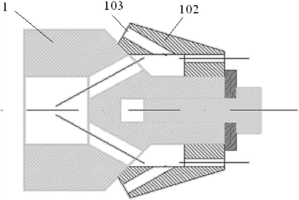
[0058] like figure 2 , the spray head 1 includes a shaft 101 connected to the dredge pipe, and a side wall 102 of the spray head arranged outside the shaft, the shaft of the spray head is provided with a rear spray hole 103, and the rear spray hole is used to push the spray head forward, There is also a backward nozzle hole on the side wall of the nozzle. The angle between the rear nozzle hole and the axis is increased, and the hole diameter is increased at the same time to test the influence of the same nozzle hole on the forward ability and cleaning ability;

[0059] The side wall 102 of the nozzle has a hollow cylindrical shape, and the side wall 102 of the nozzle has an inclination in appearance design, which improves the ability to overcome obstacles;

[0060] Increase the front spray hole 105.

[0061] Test performance:

[0062] 1. Straight pipe passing capacity: the time to pass through a standard PVC straight pipe (leng...

Embodiment 3

[0067] Embodiment 3 nozzle structure design

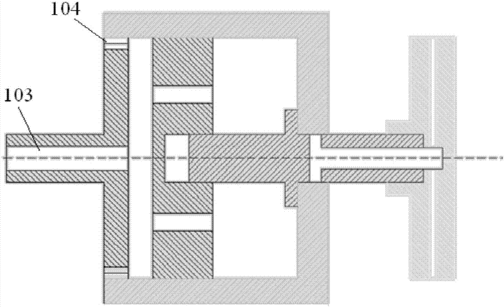
[0068] like image 3 Structurally, the rear nozzle hole 103 is used to push the nozzle forward; the side nozzle hole 104 that can rotate freely is set to test the cleaning ability and rotation ability of the side nozzle hole under different pressures.

[0069] Test performance:

[0070] 1. The nozzle maintains a good passing capacity;

[0071] 2. The side spray holes can clean the pipe wall.

[0072] problem appear:

[0073] Since the side nozzles clean the pipe wall and promote the rotation of the nozzle, the nozzle can rotate under low water pressure, but the cleaning effect is extremely poor. After increasing the water pressure, the cleaning effect is obvious, but the nozzle cannot rotate. Subsequent improvements revolve around the ability to perform spin cleaning while maintaining the forward travel and cleaning capabilities of the nozzle.


PUM


Abstract

The invention provides a pipeline dredging machine. The pipeline dredging machine comprises a water pipe; a spraying head is connected with a water pipe; the spraying head comprises a shaft part and a spraying head side wall, wherein the shaft part is connected with the water pipe, and the spraying head side wall is arranged out of the shaft part and is provided with a hollow cylindrical shape; a rear spraying hole is formed in the shaft part of the spraying head and is used for pushing the spraying head to move forward; a side spraying hole is formed in the side wall of the spraying head and is used for cleaning, and the axis of the side spraying hole is perpendicular to the axis of the rear spraying hole; and a drilling bit capable of rotating is arranged on the forefront of the spraying head and plays a role in cutting a blocking body. According to the provided pipeline dredging machine, aiming at natural deposition dredging of a buried pipeline of an outdoor railway tunnel, calcium carbonate and silt precipitated by the natural environment can be effectively dredged, the maximum dredging length of the pipeline dredging machine is up to 50 m, and the pipeline dredging machine can pass smoothly at the corners not exceeding 90 degrees; appearance design of the pipe dredging machine conforms to requirements of the tunnel using environment, and stable working of the equipment can be ensured.

Description

technical field [0001] The invention belongs to the technical field of railway construction, and in particular relates to a pipeline dredging machine used for buried pipelines in tunnels. Background technique [0002] During tunnel laying and operation, it is necessary to dredge the natural deposition of pipelines buried in outdoor railway tunnels. Due to the complex geological conditions and the erosion of karst water in the tunnel, various tunnel diseases have been caused, affecting tunnel construction or threatening traffic safety. Tunnel diseases include water leakage in the lining, damage to the foundation under the rails, etc. The thickness and strength of the lining in some sections are insufficient, and there are cavities, loose backfill, and rich water behind the lining in some sections. The damage of the foundation under the rails leads to mud and even water and mud gushing. Water gushing and mud gushing in the center ditch lead to silt deposits and poor drainage...

Claims


Application Information

Patent Timeline
Patent Type & Authority Applications(China)
IPC IPC(8): B08B9/032
CPCB08B9/0321
Inventor 马伟斌郭小雄马超锋付兵先安哲立王志伟邹文浩常凯赵鹏李尧张文达牛亚彬
Owner RAILWAY ENG RES INST CHINA ACADEMY OF RAILWAY SCI
Learn More