Motor and radiating structure thereof

A technology of heat dissipation structure and water cooler, which is applied in the direction of magnetic circuit shape/style/structure, electrical components, electromechanical devices, etc., can solve the problem of reducing the heat conduction efficiency of cooling water channel 02 and stator iron core 03, and the heat dissipation efficiency of stator iron core 03 is not high , The water-cooled casing 01 has high volume requirements, so as to avoid low positioning accuracy, improve heat conduction efficiency, and improve the processing qualification rate.

Pending Publication Date: 2017-11-21
ZHUHAI GREE REFRIGERATION TECH CENT OF ENERGY SAVING & ENVIRONMENTAL PROTECTION
View PDF7 Cites 1 Cited by
  • Summary
  • Abstract
  • Description
  • Claims
  • Application Information

AI Technical Summary

Problems solved by technology

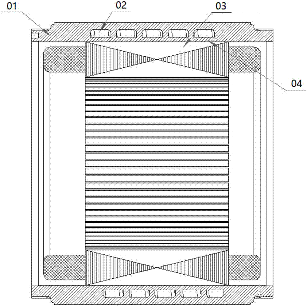
In the production process, due to the low positioning accuracy of the sand mold, the water channel of the water-cooled casing will have position deviation and leakage problems, which is inconvenient for the processing of the cooling water channel 02; moreover, the yield of the water-cooled casing is low, The highest is only 70-80%, which increases the processing cost of the water-cooled casing
The cooling water channel 02 is independently arranged in the water-cooling casing 01, so that there is a physical barrier part 03 of the water-cooling casing 01 between the cooling water channel 02 and the stator core 03, which reduces the heat transfer efficiency between the cooling water channel 02 and the stator core 03, The heat dissipation efficiency of the stator core 03 is not high
Since it is necessary to reserve a solid part of the closed cooling channel 02 on both sides (the solid part on the side close to the stator core 03 is the solid barrier part 03), the thickness of the water-cooled casing 01 is required to be relatively large, so that the water-cooled casing 01 The volume requirement is relatively high, which in turn causes the overall weight of the motor to be large, requiring a large installation space to install the motor

Method used


Image

  • Motor and radiating structure thereof
  • Motor and radiating structure thereof
  • Motor and radiating structure thereof

Examples


Embodiment Construction

[0029] The invention discloses a heat dissipation structure to improve heat dissipation efficiency, reduce weight and processing cost, save installation space, and facilitate the processing of cooling water channels. The present invention also provides a motor with the above heat dissipation structure.

[0030] The following will clearly and completely describe the technical solutions in the embodiments of the present invention with reference to the accompanying drawings in the embodiments of the present invention. Obviously, the described embodiments are only some, not all, embodiments of the present invention. Based on the embodiments of the present invention, all other embodiments obtained by persons of ordinary skill in the art without making creative efforts belong to the protection scope of the present invention.

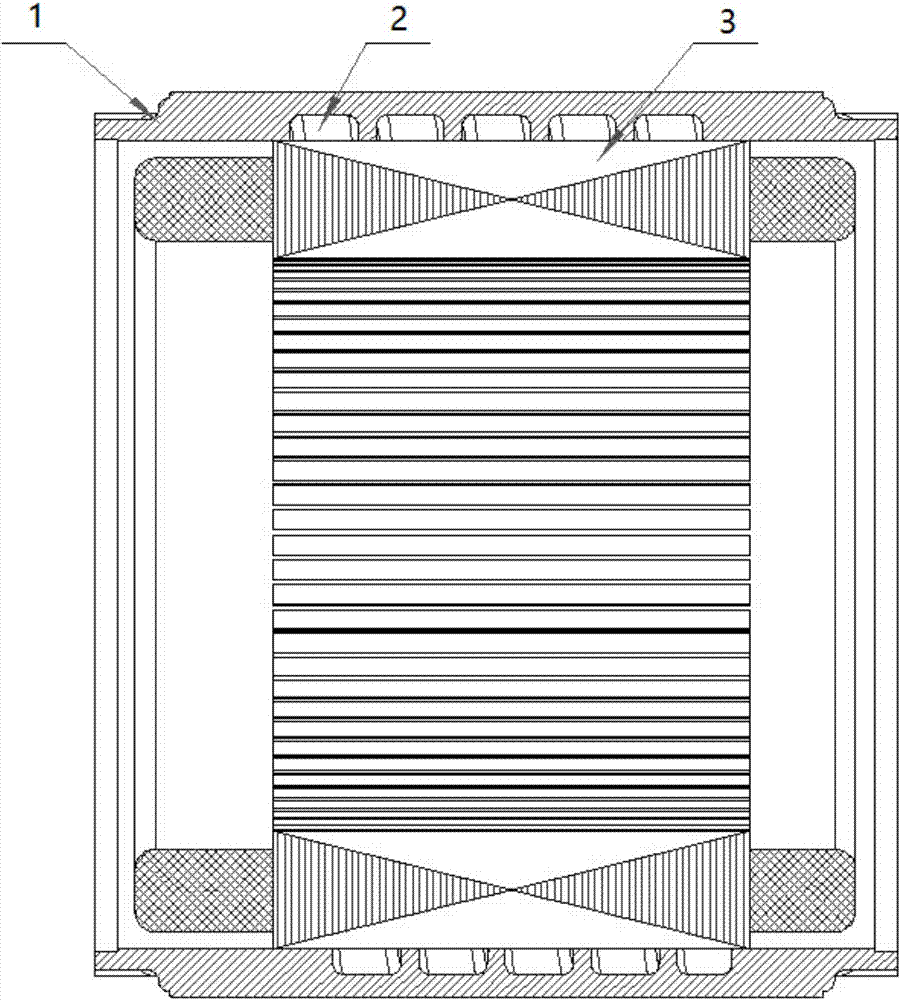
[0031] Please refer to figure 2 The embodiment of the present invention provides a heat dissipation structure, including a water-cooled casing 1 and a stato...


PUM


Abstract

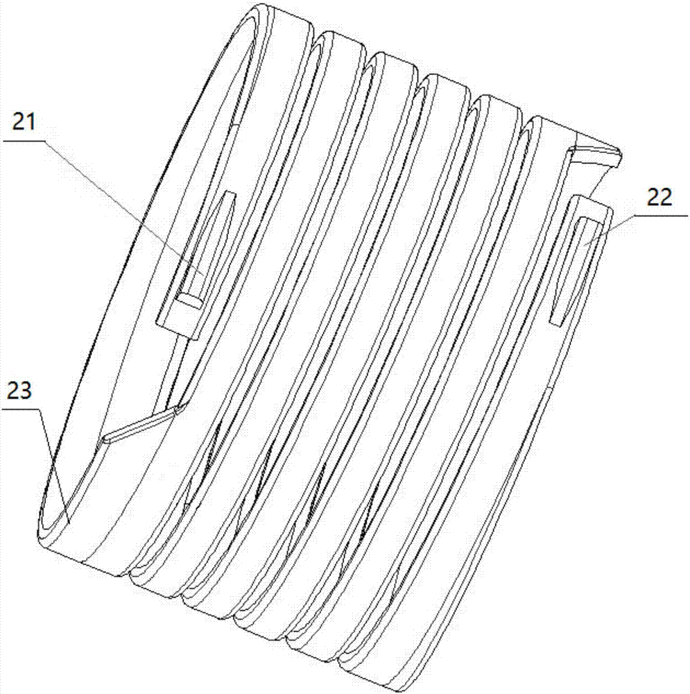
The invention discloses a motor and a radiating structure thereof. The radiating structure comprises a water cooling shell (1) and a stator core (3); cooling water tanks are arranged on at least one of a water cooling fitting surface of the water cooling shell (1) facing to the stator core (3) and an iron core fitting surface of the stator core (3) facing to the water cooling shell (1); and the cooling water tank on one fitting surface is matched with the other fitting surface so as to form a cooling water channel (2). The radiating structure provided by the invention can effectively increase the heat conduction efficiency of the stator core, so that the radiating efficiency of the stator core can be effectively promoted; the volume requirement of the water cooling shell is effectively reduced, so that the overall weight of the motor is reduced, the structure compactness is increased, the motor power density is increased and the mounting space is saved; and the processing of the cooling water channel is convenient and the processing yield of the cooling water channel is increased, so that the processing cost is lowered.

Description

technical field [0001] The invention relates to the technical field of motor equipment, in particular to a motor and its heat dissipation structure. Background technique [0002] As a common driving device, the motor has been widely used. During the operation of the motor, heat will inevitably be generated, and if the temperature of the motor is too high, the efficiency and safety of the motor will be greatly affected. Therefore, the motor needs to be cooled. [0003] Such as figure 1 As shown, the motor in this figure is an automobile drive motor, which generally adopts a liquid cooling structure as a heat dissipation structure. The heat dissipation structure includes the stator core 03 and the water-cooled casing 01 in thermal contact with the stator core 03. The interior of the water-cooled casing 01 is generally formed by low-pressure casting in the form of a combination of sand mold and steel mold. Casting needs to put the sand mold into the mold and cast together. A...

Claims


Application Information

Patent Timeline
Patent Type & Authority Applications(China)
IPC IPC(8): H02K5/20H02K1/20H02K9/19
CPCH02K1/20H02K5/20H02K9/19
Inventor 郭长光张小波刘健宁贾金信张芳李广海李忠雨魏琼闫瑾彭利明
Owner ZHUHAI GREE REFRIGERATION TECH CENT OF ENERGY SAVING & ENVIRONMENTAL PROTECTION
Why Eureka
Try Eureka