
Wafer Planarization Method

A flattening method and wafer technology, applied in the manufacture of electrical components, circuits, semiconductor/solid-state devices, etc., can solve the problem that cerium oxide abrasive particles are easy to remain on the surface of silicon wafers

Active Publication Date: 2020-02-21
SHANGHAI HUAHONG GRACE SEMICON MFG CORP
View PDF5 Cites 0 Cited by
  • Summary
  • Abstract
  • Description
  • Claims
  • Application Information

AI Technical Summary

Problems solved by technology

[0005] The object of the present invention is to provide a wafer planarization method to solve the problem that cerium oxide abrasive particles are likely to remain on the surface of the silicon wafer during the process of wafer grinding with cerium oxide abrasive liquid for planarization

Method used


Image

  • Wafer Planarization Method
  • Wafer Planarization Method

Examples


Embodiment Construction

[0024] A specific implementation of a wafer planarization method provided by the present invention will be described in more detail below with reference to schematic diagrams. Advantages and features of the present invention will be apparent from the following description and claims. It should be noted that all the drawings are in a very simplified form and use imprecise scales, and are only used to facilitate and clearly assist the purpose of illustrating the embodiments of the present invention.

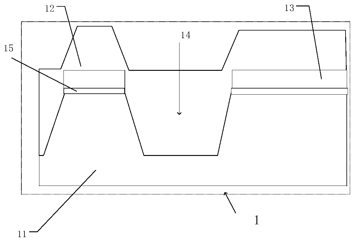
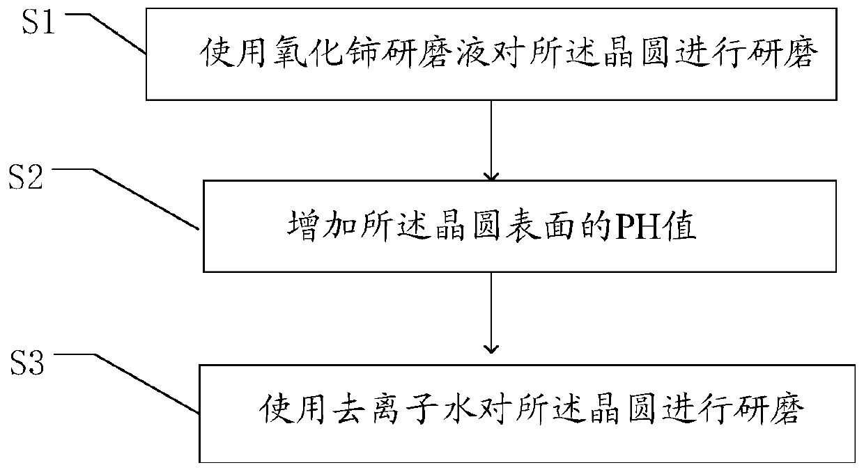
[0025] refer to Figure 1-Figure 2 , which is a schematic diagram of the wafer structure provided by the present invention and a wafer planarization method, the wafer 1 includes a substrate 11 and an oxide layer 12; a trench 14 is formed in the substrate 11, and the oxide layer 12 covering the substrate 11 and filling the trench 14, grinding the wafer 1 on a polishing pad to planarize the wafer 1, the method for planarizing the wafer 1 includes, S1: using Grinding the wafer 1 wit...


PUM

PropertyMeasurementUnit
thicknessaaaaaaaaaa
thicknessaaaaaaaaaa

Abstract

The invention provides a method for flattening a wafer. The wafer comprises a substrate and an oxide layer, wherein the substrate is provided with a trench, and the oxide layer covers the substrate and fills the trench. The wafer is ground by using a cerium oxide grinding solution, thereby being capable effectively overcoming a defect of recesses, and having better on-chip flatness and a lower discarding degree. In addition, scratches at the surface of the wafer are small, thereby being conducive to flattening; the PH value of the surface of the wafer is increased, thereby being capable of effectively reducing the adhesion of cerium oxide particles, reducing the cerium oxide particles adhered to the surface of the wafer, and being conducive to subsequent cleaning for the wafer; and the wafer is ground by using deionized wafer so as to wash out the cerium oxide particles and other impurities adhered to the surface of the wafer. The whole technological process is very simple. In addition, subsequent detection for the wafer is more accurate, and the yield of the chip is improved.

Description

technical field [0001] The invention relates to the field of semiconductor manufacturing, in particular to a wafer planarization method. Background technique [0002] In the semiconductor manufacturing process, the planarization process is one of the indispensable process steps, and its ability directly affects the flatness of the wafer surface, which in turn affects the yield of the product. [0003] Shallow trench isolation (STI) is a front-end process used to form isolation regions between devices on the surface of a silicon wafer. The filling oxide layer in STI is to use planarization technology to grind away all the oxide layers higher than the barrier layer, so as to realize flattened. One difficulty with STI planarization is how to avoid too much oxide thinning, or dishing, in the trenches. The sinking phenomenon will cause many negative effects on the device, such as lower gate voltage, increased leakage and so on. In the prior art, in order to solve the defects o...

Claims


Application Information

Patent Timeline
Patent Type & Authority Patents(China)
IPC IPC(8): H01L21/304
CPCH01L21/304
Inventor 吴建荣李儒兴
Owner SHANGHAI HUAHONG GRACE SEMICON MFG CORP
Learn More