Automatic dosing and beating system

A technology of automatic batching and beating bucket, which is applied in textile processing machine accessories, textile material processing, and textile material processing equipment configuration, etc. The problem is to achieve the effect of good chopping effect, good effect and obvious beating effect.

Inactive Publication Date: 2017-11-21
HUZHOU CHENGXIN TEXTILE PRINTING & DYEING
View PDF1 Cites 3 Cited by
  • Summary
  • Abstract
  • Description
  • Claims
  • Application Information

AI Technical Summary

Problems solved by technology

[0004] The purpose of the present invention is to address the deficiencies of the prior art, by arranging cutter a and cutter b to form a shear channel and cooperate with the rotating cutter c to shear the slurry and then spray the fully beaten slurry Spray onto the textile fibers in a unique way to overcome the problems of insufficient beating of the sizing material, poor fineness of the sizing material and uneven sizing of the sizing material

Method used


Image

  • Automatic dosing and beating system
  • Automatic dosing and beating system
  • Automatic dosing and beating system

Examples


Embodiment 1

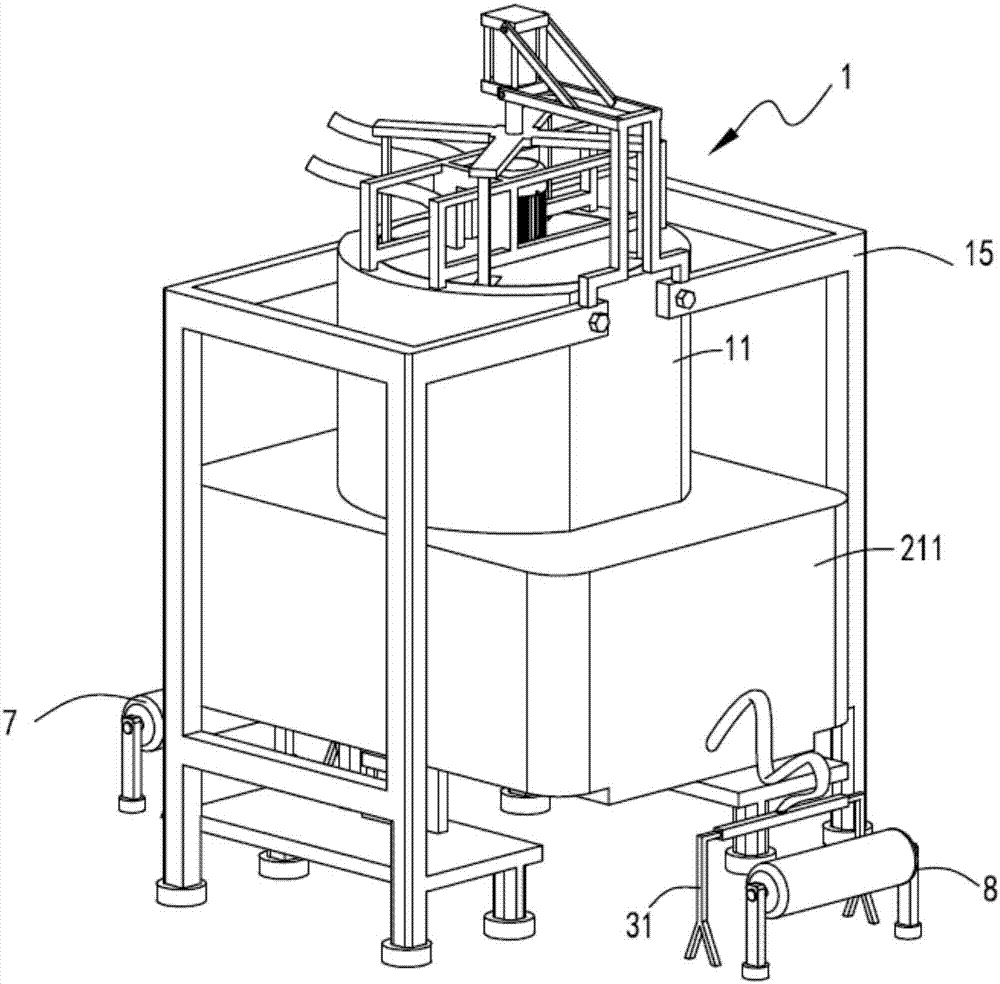
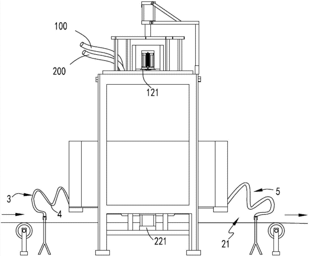
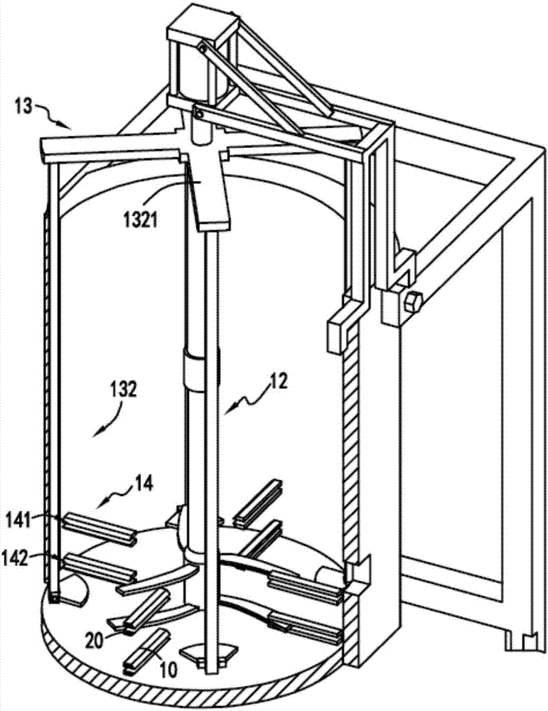
[0040] figure 1 It is a schematic diagram of the structure of the automatic batching and beating system, figure 2 It is a schematic diagram of the front view of the automatic batching and beating system, image 3 It is a schematic diagram of the internal structure of the beating part, Figure 4 It is a schematic diagram of the cut-away structure of the beating device, Figure 5 It is a schematic diagram of the enlarged structure of the cutter mechanism, Image 6 It is a partial top view schematic diagram of the beating part, Figure 7 A cutaway diagram of the control mechanism, Figure 8 is a cut-away schematic diagram of the guide channel, Figure 9 is a schematic diagram of the structure of the stirrer, Figure 10 It is a partial structural schematic diagram of the stirring part and the drying part, Figure 11 It is an enlarged schematic diagram of part of the structure of the injection parts, such as figure 1 , figure 2 , image 3 , Figure 4 , Figure 5 , I...

Embodiment 2

[0057] like figure 1 , figure 2 , image 3 , Figure 4 , Figure 5 , Image 6 , Figure 7 , Figure 8 , Figure 9 , Figure 10 and Figure 11 As shown, the components that are the same as or corresponding to those in the first embodiment are marked with the corresponding reference numerals in the first embodiment. For the sake of simplicity, only the differences from the first embodiment will be described below. The difference between the second embodiment and the first embodiment is that the thickness of the cutter c123 is d1, the height of the shear channel 30 is d2, d1 and d2 satisfy d1=d2, the cutter a10 and the cutter One end of the knife b20 close to the entrance of the shearing channel 30 is provided with a knife edge, and correspondingly, knife edges are provided at the upper and lower ends of the front side of the cutter c123.

[0058] First, by setting two cutting edges corresponding to the cutting edges on the cutting knife a10 and the cutting knife b20 o...


PUM


Abstract

The invention relates to an automatic batching and beating system, comprising a beating part, the beating part includes a beating barrel, a rotating chopping mechanism and an agitating mechanism, the beating barrel is fixed on a bracket, and the inner wall of the beating barrel is provided with several cutter mechanisms along its circumferential direction , during the rotation of the rotating shredding mechanism, cooperate with the cutter mechanism to cut the fibers in the slurry, the stirring mechanism is arranged on one side of the cutter mechanism, and the stirring mechanism is used to stir the slurry up and down; the sizing part The sizing part includes a sizing mechanism arranged under the beating barrel and a control mechanism arranged under the sizing mechanism. The sizing mechanism is used to accept the slurry flowing out of the beating barrel and transmit it from the front and rear ends under the action of the control mechanism. Spraying the sizing solution twice on the textile fiber; the invention overcomes the problems of insufficient beating of the sizing material, poor fineness of the sizing material and uneven sizing of the sizing material.

Description

technical field [0001] The invention relates to the technical field of textile beating equipment, in particular to an automatic batching and beating system. Background technique [0002] At present, the beater is more and more favored by people because of its convenient use and fast refining, but the particles pulverized by the beating knife of the beater are relatively large, there are more residues, and the crushing effect is poor. The pulverizing effect of the knife depends on the shape of the beating knife and the relevant parameters of the beating knife, so how to make the pulverizing effect of the beating knife and the adequacy of beating become an urgent problem to be solved at present. [0003] Authorized notification number CN204743871U is a Chinese utility model patent, which discloses a beating knife and a beating machine, wherein the beating knife is used for the beating machine, and the blade of the beating knife is provided with a plurality of stepped Arranged...

Claims


Application Information

Patent Timeline
Patent Type & Authority Applications(China)
IPC IPC(8): D06B1/02D06B23/20B02C18/18B02C18/10
CPCD06B1/02B02C18/10B02C18/18D06B23/205
Inventor 王利春
Owner HUZHOU CHENGXIN TEXTILE PRINTING & DYEING
Why Eureka
Try Eureka