
A cutting device for workpiece blank

A cutting device and blank technology, applied in positioning devices, metal processing machinery parts, manufacturing tools, etc., can solve the problems of no waste slag treatment, heavy weight, processing errors, etc., and achieve high practicability, convenient operation, and improved processing quality. Effect

Active Publication Date: 2019-02-26
ANHUI TONGSHENG RING
View PDF6 Cites 0 Cited by
  • Summary
  • Abstract
  • Description
  • Claims
  • Application Information

AI Technical Summary

Problems solved by technology

In the prior art, when processing large workpieces, such as drilling, cutting and surface cutting, it is necessary to fix the large workpiece blanks. However, due to the heavy weight of the large workpiece blanks, it is inconvenient to fix and position them. During processing, it is easy to cause the dimensional accuracy of the large workpiece to be processed to be low, especially when cutting, because the chip knife exerts cutting force on the blank, causing the blank to be fixed unstable and shaking, resulting in machining errors
[0003] Patent No. 201620101199.1 provides a large-scale ring blank cutting equipment, the upper end surface of the base is provided with a rotating disk, the rotating disk is connected to the output shaft of the driving device, the driving device is arranged on the base, the lower end of the support frame Fixed on the base, the support frame is provided with a transversely movable beam and a vertical fixed plate, the vertical fixed plate is arranged on the beam through a sliding block, the cutter box is provided on the vertical fixed plate, and the cutter box is on the vertical fixed plate. The straight fixed plate controls the up and down movement through the ball screw mechanism. The edge of the base has an upwardly extending part. Rollers are arranged between the extending part and the side of the rotating disk. The rollers are arranged on the extending part of the base for rolling. The above-mentioned rotating disk is provided with fixed feet evenly distributed around the circumference, and the upper end of the base is provided with an anti-swarf baffle, which cannot effectively and timely dispose of the waste residue generated at the end of cutting, and has certain disadvantages

Method used


Image

  • A cutting device for workpiece blank
  • A cutting device for workpiece blank
  • A cutting device for workpiece blank

Examples


Embodiment Construction

[0021] The following will clearly and completely describe the technical solutions in the embodiments of the present invention with reference to the accompanying drawings in the embodiments of the present invention. Obviously, the described embodiments are only some, not all, embodiments of the present invention. Based on the embodiments of the present invention, all other embodiments obtained by persons of ordinary skill in the art without creative efforts fall within the protection scope of the present invention.

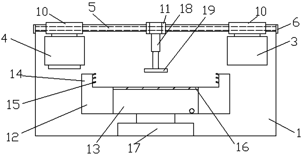
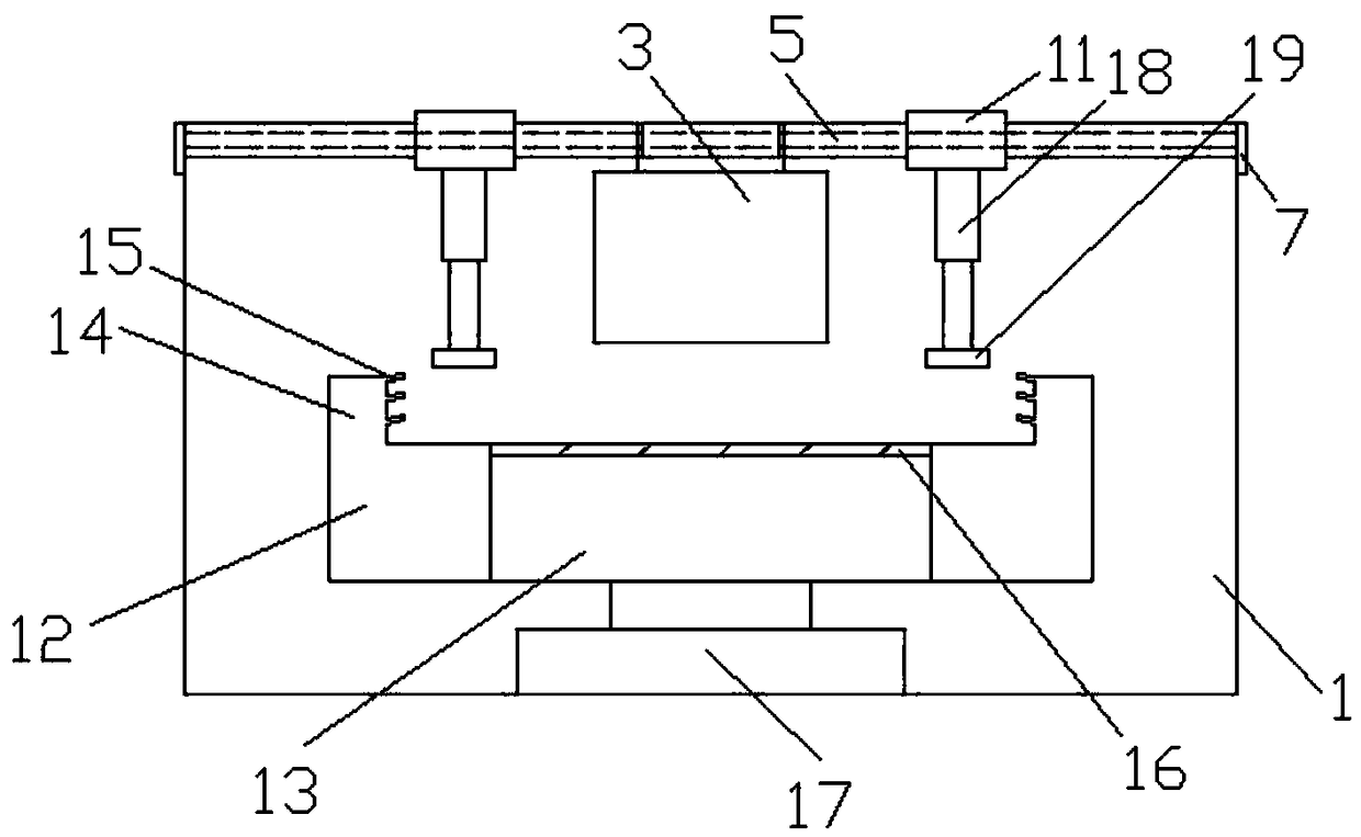
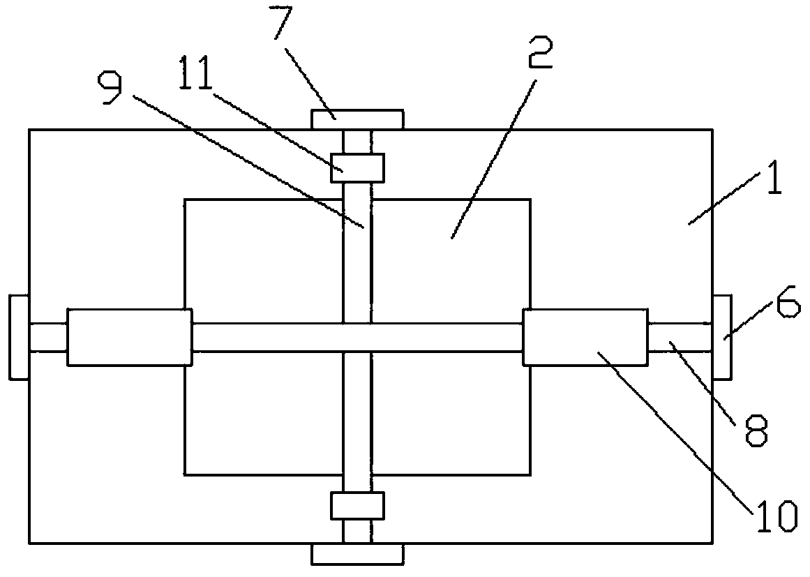
[0022] Such as Figure 1 ~ Figure 3 As shown, a cutting device for workpiece blanks includes a frame 1, a workbench 2, a cutter box 3, a magnet block 4 and a fixing mechanism. The upper part of the frame 1 is provided with a slide rail 5, and the slide rail 5 is provided Sliding block, the sliding block is divided into sliding block I6 and sliding block II7, there are two sliding blocks I6 and sliding block II7, the sliding bar I8 is connected between the sliding b...


PUM


Abstract

The invention relates to the technical field of machine part production devices, in particular to a cutting device for workpiece blanks. The cutting device for the workpiece blanks comprises a machine frame, a workbench, a cutter box, a magnetic block and a fixing mechanism, wherein a sliding rail is arranged on the upper portion of the machine frame; sliding blocks are arranged in the sliding rail and comprise the first sliding blocks and the second sliding blocks; a first sliding rod is connected between the first sliding blocks; a second sliding rod is connected between the second sliding blocks; a first sliding sleeve is arranged on the first sliding rod, and a second sliding sleeve is arranged on the second sliding rod; a clean water chamber and a waste water chamber are arranged inside the workbench; the cutter box and the magnetic block are arranged on the first sliding sleeve; and the fixing mechanism is arranged on the second sliding sleeve. According to the cutting device for the workpiece blanks, the workpiece blanks can be fixed at first, so that the situation that the workpiece blanks shake in the cutting process and consequently machining errors are caused and the product quality is affected is avoided; the workpiece surfaces can be cleaned through the clean water chamber in the machining process, and it is ensured that the workpiece blanks are clearly visible in the machining process; and the positions of the cutter box, the magnetic block and the fixing mechanism can be adjusted as required, operation is convenient, and practicability is high.

Description

technical field [0001] The invention relates to the technical field of mechanical parts production equipment, and more specifically relates to a cutting device for workpiece blanks. Background technique [0002] Large mechanical workpieces are important mechanical parts and are often used as finished products or raw materials in numerous mechanical processing and production technology fields. In the prior art, when processing large workpieces, such as drilling, cutting and surface cutting, it is necessary to fix the large workpiece blanks. However, due to the heavy weight of the large workpiece blanks, it is inconvenient to fix and position them. During processing, it is easy to cause the dimensional accuracy of the large workpiece to be processed to be low, especially when cutting, because the chip knife applies cutting force to the blank, causing the blank to be unstable and shake, resulting in machining errors. [0003] Patent No. 201620101199.1 provides a large-scale ri...

Claims


Application Information

Patent Timeline
Patent Type & Authority Patents(China)
IPC IPC(8): B23Q3/06B23Q11/00
CPCB23Q3/06B23Q11/0042
Inventor 蔡锟赵卓
Owner ANHUI TONGSHENG RING
Learn More