Battery module welding method

A battery module and welding method technology, applied in battery pack parts, welding equipment, battery assembly machines, etc., can solve the problems of small solder joint area, desoldering, false soldering rate, etc., to improve production efficiency, The effect of improving corrosion resistance and ensuring welding quality

Inactive Publication Date: 2017-11-21
伍伟东 +1
View PDF4 Cites 7 Cited by
  • Summary
  • Abstract
  • Description
  • Claims
  • Application Information

AI Technical Summary

Problems solved by technology

Among them, resistance welding is to combine the bus plate with the positive and negative electrodes of the battery and apply pressure through the electrodes, and use the resistance heat generated by the current passing through the contact surface of the joint and the adjacent area for welding. Disadvantages such as low rate, low tensile strength of welding points, desoldering, false welding and high rate of false welding
In addition, the battery module using resistance welding is difficult to disassemble in the subsequent cascade utilization process, and needs to be polished after disassembly, and the grinding will damage the anti-rust coating of the battery, thereby affecting the firmness of the secondary welding
[0003] Manual soldering is mostly used for manual soldering of high-temperature ferrochrome with tin wire, which has disadvantages such as low efficiency and inability to accurately control heating time.
If the heating time is too long during the welding process, the battery will be thermally damaged, and the above welding methods have no corresponding automatic detection methods during and after welding, which cannot ensure the welding quality

Method used


Image

  • Battery module welding method
  • Battery module welding method
  • Battery module welding method

Examples


Embodiment Construction

[0022] In order to make the object, technical solution and beneficial technical effects of the present invention clearer, the present invention will be further described in detail below in conjunction with the accompanying drawings and specific embodiments. It should be understood that the specific implementations described in this specification are only for explaining the present invention, not for limiting the present invention.

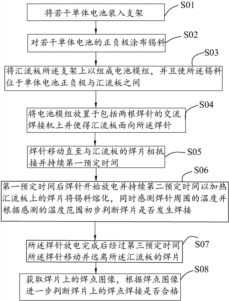
[0023] see figure 1 , which is a flowchart of a battery module welding method provided by the present invention. It should be noted that the method of the present invention is not limited to the order of the following steps, and in other embodiments, the method of the present invention may only include some of the steps described below, or some of the steps may be replaced by delete. The welding method of the battery module provided by the present invention comprises the following steps:

[0024] Step S01, loading several single batteries into t...


PUM

PropertyMeasurementUnit
diameteraaaaaaaaaa
diameteraaaaaaaaaa
melting pointaaaaaaaaaa

Abstract

The invention provides a battery module welding method. The battery module welding method comprises the following steps that a plurality of single batteries are loaded in supports; positive and negative poles of the multiple single batteries are coated with tin materials; confluence plates are fixed to the supports, so that a battery module is constituted, and the tin materials are located between the positive and negative poles of the single batteries and the confluence plates; the battery module is placed on an alternating current welder comprising two welding pins, and the confluence plates face the welding pins; the welding pins are moved to abut against welding pieces on the confluence plates for the first predetermined time; after the first predetermined time, the welding pins start to discharge electricity for the second predetermined time, so that the welding pieces on the confluence plates are heated, the tin materials are melted, meanwhile, the temperature around the welding pins are sensed, and whether the welding pieces and the single batteries are welded or not is preliminarily judged according to the sensed temperature range; after discharging the electricity, the welding pins stop for the third predetermined time, and then are moved and are away from the welding pieces on the confluence plates; and images of welding points on the welding pieces are obtained, and whether the welding points of the welding pieces are qualified or not is judged according to the welding point images.

Description

【Technical field】 [0001] The invention relates to the technical field of battery package welding, in particular to a battery module welding method. 【Background technique】 [0002] At present, in the process of battery manufacturing and packaging, for example, in the process of welding the manifold and the positive and negative electrodes of the single battery, resistance welding or manual soldering is usually used to achieve. Among them, resistance welding is to combine the bus plate with the positive and negative electrodes of the battery and apply pressure through the electrodes, and use the resistance heat generated by the current passing through the contact surface of the joint and the adjacent area for welding. Low rate, low tensile strength of welding points, desoldering, false welding and high rate of false welding. In addition, the battery module using resistance welding is difficult to disassemble in the subsequent cascade utilization process, and needs to be polis...

Claims


Application Information

Patent Timeline
Patent Type & Authority Applications(China)
IPC IPC(8): B23K1/00B23K3/00B23K3/08B23K37/02H01M2/20H01M2/22B23K101/38H01M50/516H01M50/528
CPCH01M10/0404B23K1/0008B23K1/0016B23K1/0056B23K1/203B23K3/00B23K3/0692B23K3/08B23K3/087B23K37/0252B23K2101/38B23K2101/36H01M50/502H01M50/528H01M50/531Y02E60/10Y02P70/50
Inventor 伍伟东夏先坤
Owner 伍伟东
Why Eureka
Try Eureka