Welding device for battery module

A battery module and welding device technology, which is applied to battery pack components, auxiliary devices, tin feeding devices, etc., can solve the problems of desoldering, small solder joint area, false soldering and false soldering rate, etc., and improve the anti-corrosion ability , the effect of improving production efficiency

Inactive Publication Date: 2017-10-20
伍伟东 +1
View PDF14 Cites 14 Cited by
  • Summary
  • Abstract
  • Description
  • Claims
  • Application Information

AI Technical Summary

Problems solved by technology

Among them, resistance welding is to combine the bus plate with the positive and negative electrodes of the battery and apply pressure through the electrodes, and use the resistance heat generated by the current passing through the contact surface of the joint and the adjacent area for welding. Disadvantages such as low rate, low tensile strength of welding points, desoldering, false welding and high rate of false welding
In addition, the battery module using resistance welding is difficult to disassemble in the subsequent cascade utilization process, and needs to be polished after disassembly, and the grinding will damage the anti-rust coating of the battery, thereby affecting the firmness of the secondary welding
[0003] Manual soldering is mostly used for manual soldering of high-temperature ferrochrome with tin wire, which has disadvantages such as low efficiency and inability to accurately control heating time.
If the heating time is too long during the welding process, the battery will be thermally damaged

Method used


Image

  • Welding device for battery module
  • Welding device for battery module

Examples


Embodiment Construction

[0010] In order to make the object, technical solution and beneficial technical effects of the present invention clearer, the present invention will be further described in detail below in conjunction with the accompanying drawings and specific embodiments. It should be understood that the specific implementations described in this specification are only for explaining the present invention, not for limiting the present invention.

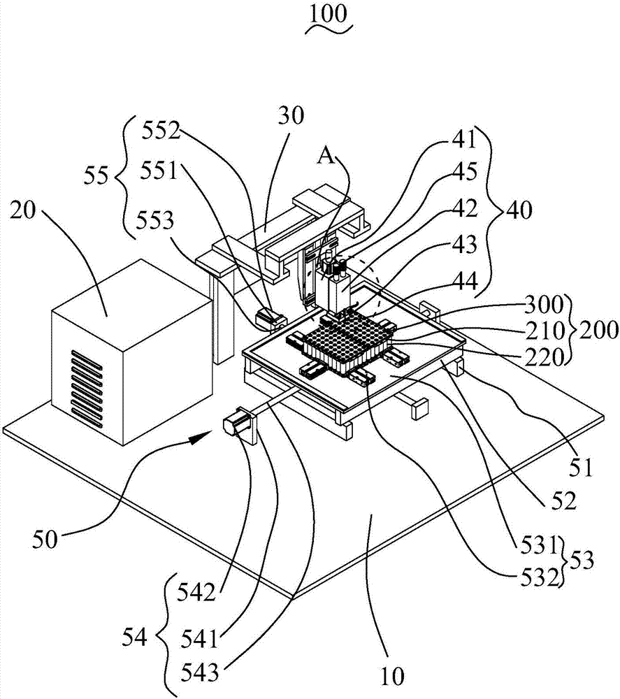
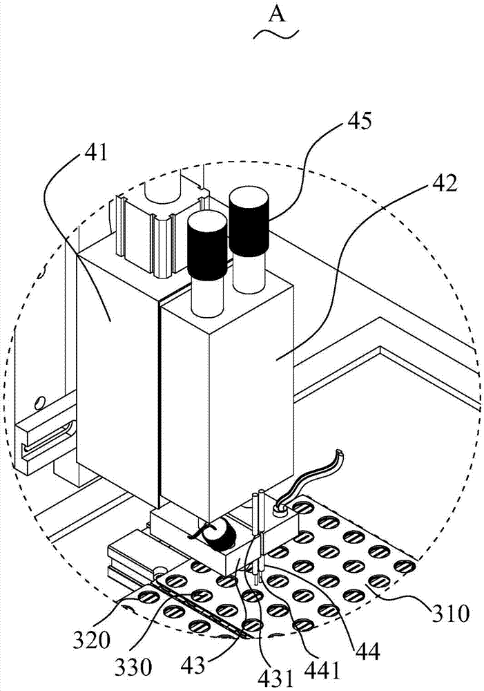
[0011] Please also refer to Figure 1-2 , which is a perspective view of the battery module welding device 100 provided by the present invention. The battery module welding device 100 is used for welding the battery module 200 . Wherein, the battery module 200 includes a pair of brackets 210 arranged at intervals, a number of single cells 220 fixed at both ends of the two brackets 210, and a plurality of single cells 220 respectively fixed on the two brackets 210 and close to the plurality of cells. The bus plate 300 on the end face of the bulk b...


PUM

PropertyMeasurementUnit
diameteraaaaaaaaaa

Abstract

The invention provides a welding device for a battery module. The welding device is used for welding the battery module. The welding device for the battery module comprises a base, a welding mechanism and a moving mechanism; the welding mechanism comprises a driving part, a first sliding block, two second sliding blocks and two welding needles; the driving part is used for driving the first sliding block to slide relative to the driving part; the two second sliding blocks are arranged on one side of the first sliding block side by side, are close to the moving mechanism and can move in the direction of being close to or far away from the moving mechanism under driving of the first sliding block; the battery module is installed on the moving mechanism, enables a bus board to face the welding needles and can move in the first direction and the second direction relative to the base under driving of the moving mechanism; the two welding needles are installed on the two sliding blocks respectively and release alternating currents to melt solder when the welding needles are connected with the bus board in a butted mode, and then the bus board and a plurality of single batteries are welded. According to the welding device for the battery module, the defects existing in electric resistance welding and manual soldering are overcome.

Description

【Technical field】 [0001] The invention relates to the technical field of battery package welding, in particular to a battery module welding device. 【Background technique】 [0002] At present, in the process of battery manufacturing and packaging, for example, in the process of welding the manifold and the positive and negative electrodes of the single battery, resistance welding or manual soldering is usually used to achieve. Among them, resistance welding is to combine the bus plate with the positive and negative electrodes of the battery and apply pressure through the electrodes, and use the resistance heat generated by the current passing through the contact surface of the joint and the adjacent area for welding. Low rate, low tensile strength of welding points, desoldering, false welding and high rate of false welding. In addition, the battery module using resistance welding is difficult to disassemble in the subsequent cascade utilization process, and needs to be polis...

Claims


Application Information

Patent Timeline
Patent Type & Authority Applications(China)
IPC IPC(8): B23K3/00B23K3/08B23K37/04B23K37/02B23K1/005H01M2/20H01M2/22H01M10/04H01M50/516H01M50/528
CPCH01M10/0404B23K1/0008B23K1/0016B23K1/0056B23K1/203B23K3/00B23K3/0692B23K3/08B23K3/087B23K37/0252B23K2101/38B23K2101/36H01M50/502H01M50/528H01M50/531Y02E60/10Y02P70/50
Inventor 伍伟东夏先坤
Owner 伍伟东
Why Eureka
Try Eureka