
Steel bar cutting machine with steel bar fixing function

A fixed function, cutting machine technology, applied in the field of steel bar cutting machine, can solve the problems of affecting the effect of steel bar cutting, consuming large manpower for steel bars, environmental pollution, etc., to achieve the effect of improving the effect, improving the practicability, and avoiding pollution.

Inactive Publication Date: 2017-11-21
梅芹
View PDF3 Cites 14 Cited by
  • Summary
  • Abstract
  • Description
  • Claims
  • Application Information

AI Technical Summary

Problems solved by technology

[0003] Generally, before the steel bar is used, in order to obtain the steel bar of suitable size, the steel bar is usually cut. The existing steel bar cutting machine can not effectively fix the steel bar when cutting the steel bar, so the steel bar is easy to move during cutting and thus It affects the effect of steel bar cutting. At the same time, it is very inconvenient to move the steel bar on the steel bar cutting machine. It takes a lot of manpower to move the steel bar. At the same time, the waste chips generated during the steel bar cutting process are scattered around, causing certain pollution to the environment.

Method used


Image

  • Steel bar cutting machine with steel bar fixing function
  • Steel bar cutting machine with steel bar fixing function
  • Steel bar cutting machine with steel bar fixing function

Examples


Embodiment Construction

[0017] The following will clearly and completely describe the technical solutions in the embodiments of the present invention with reference to the accompanying drawings in the embodiments of the present invention. Obviously, the described embodiments are only some, not all, embodiments of the present invention. Based on the embodiments of the present invention, all other embodiments obtained by persons of ordinary skill in the art without making creative efforts belong to the protection scope of the present invention.

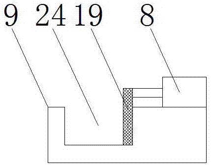
[0018] see Figure 1~3 , in an embodiment of the present invention, a steel bar cutting machine with a steel bar fixing function includes a support arm 1, a first cylinder 2, a hydraulic telescopic rod 3, a rotating shaft 5, a first support rod 6, a cutting blade 7, and a second cylinder 8 , support plate 9, support 11, base plate 15, support leg 16, electric control switch 17, push plate 19, pressing plate 20, second support bar 21 and cutting motor 22, descr...


PUM


Abstract

The invention discloses a steel bar cutting machine with a steel bar fixing function. The steel bar cutting machine comprises a groove, a supporting flat plate, a first air cylinder, an antiskid mat, a cutting motor, a hydraulic cylinder and a waste chip collection groove. The groove is formed to be used for containing one end of a to-be-cut steel bar; when the steel bar needs to move, the supporting flat plate is pulled, then the steel bar is driven to move at the top of a bottom plate, and rapid movement of the steel bar at the top of the bottom plate is achieved; the first air cylinder is firstly utilized for driving a press plate to move downwards to extrude and fix the steel bar; the cutting motor rotates, then a cutting blade on a rotary shaft is driven to rotate, and therefore the steel bar is cut; the hydraulic cylinder continues to drive a hydraulic rod to move downwards, and then cutting of the steel bar is completed; and the waste chip collection groove is formed to be used for collecting waste chips generated when the steel bar is cut, the situation that the environment is contaminated due to the fact that the waste chips are scattered around is avoided, and the practicality of equipment is improved.

Description

technical field [0001] The invention relates to a steel bar cutting machine, in particular to a steel bar cutting machine with a steel bar fixing function. Background technique [0002] Reinforcement refers to steel for reinforced concrete and prestressed reinforced concrete, which is circular in cross-section and sometimes square with rounded corners. Including plain round bars, ribbed bars, twisted bars. The steel bar for reinforced concrete refers to the straight or coiled steel used for reinforced concrete reinforcement. Its shape is divided into two types: smooth round steel bar and deformed steel bar, and the delivery state is straight and coiled. [0003] Generally, before the steel bar is used, in order to obtain the steel bar of suitable size, the steel bar is usually cut. The existing steel bar cutting machine can not effectively fix the steel bar when cutting the steel bar, so the steel bar is easy to move during cutting and thus It affects the effect of steel b...

Claims


Application Information

Patent Timeline
Patent Type & Authority Applications(China)
IPC IPC(8): B21F11/00
CPCB21F11/00
Inventor 梅芹
Owner 梅芹
Learn More