
Stepped milling cutter

A milling cutter and step technology, applied in the field of step milling cutters, can solve the problems of surface quality not meeting the processing requirements, high production costs, low processing efficiency, etc., to reduce the risk of blade breakage, save processing time and tool setting. The effect of time and blade strength enhancement

Active Publication Date: 2017-11-17
ZHUZHOU CEMENTED CARBIDE CUTTING TOOLS CO LTD
View PDF7 Cites 7 Cited by
  • Summary
  • Abstract
  • Description
  • Claims
  • Application Information

AI Technical Summary

Problems solved by technology

However, this kind of processing technology has low processing efficiency, and there are strict requirements on the fillet at the root of the step (the fillet should not be greater than R0.02mm).
[0003] With the compression of mobile phone profits, the original processing technology cannot meet the requirements of low cost. Therefore, there are ordinary one-time processing of stepped holes instead of the original processing technology in the market. However, ordinary conventional stepped milling cutters are used to process stepped holes. , there is a risk of severe milling cutter breakage and increased scrap rate, so that the production cost remains high

Method used


Image

  • Stepped milling cutter
  • Stepped milling cutter
  • Stepped milling cutter

Examples


Embodiment Construction

[0028] The present invention will be described in further detail below in conjunction with the accompanying drawings and specific embodiments.

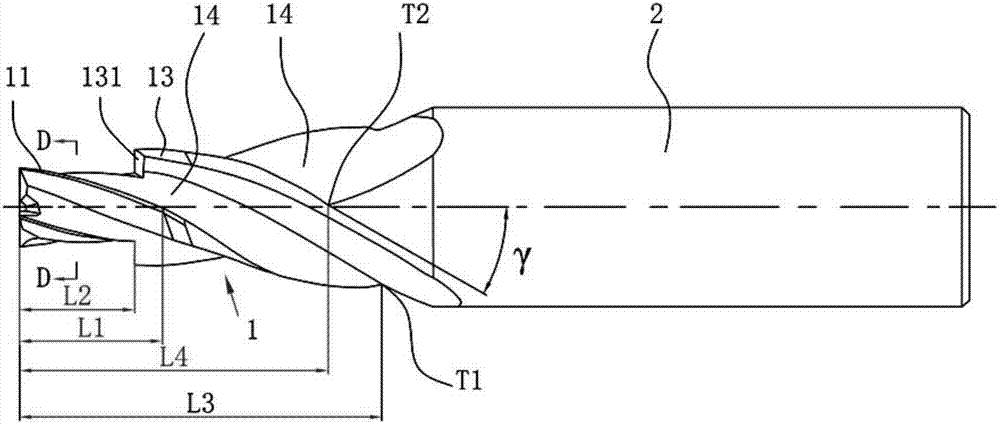
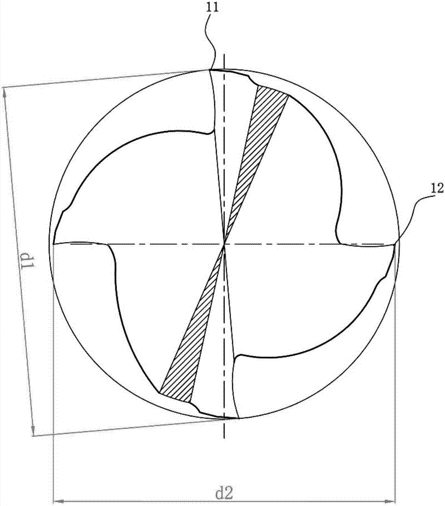
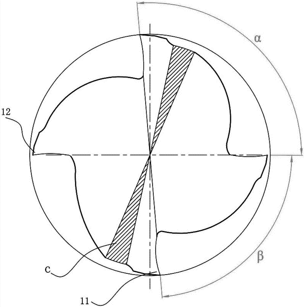
[0029] Figure 1 to Figure 4 An embodiment of the stepped milling cutter of the present invention is shown, the stepped milling cutter comprises a tool holder 2 and a cutting part 1, the cutting part 1 comprises four main edges and four helical flutes 14, each main edge is provided with a step Edge 13, the diameter of one pair of main blades in the four main blades is greater than the diameter of the other pair of main blades, and the main blade with a large diameter is the first peripheral blade 11, the small diameter of the main blade is the second peripheral blade 12, the first The length of the peripheral cutting edge 11 is greater than the length of the second peripheral cutting edge 12 . The outer diameter of the first peripheral cutting edge 11 is larger than that of the second peripheral cutting edge 12, in order to ensure th...


PUM


Abstract

The invention discloses a stepped milling cutter. The stepped milling cutter comprises a cutter handle and a cutting part. The cutting part comprises four main cutting edges and four spiral chip removal grooves, each main cutting edge is provided with a steeped cutting edge, the diameter of the two of the four main cutting edges is larger than that of the other two main cutting edges, the large-diameter main cutting edges serve as first circumferential cutting edges, the small-diameter main cutting edges serve as second circumferential cutting edges, and the length of the first circumferential cutting edges is larger than that of the second circumferential cutting edges. According to the stepped milling cutter, the first circumferential cutting edges and the second circumferential cutting edges are different in the outer diameter and are arranged in a staggered mode, so that cutting faces are crossed to form a right-angle step forming face, and the effect that the step root of an IO interface groove of a mobile phone meets the strict rounded corner requirement can be ensured; and by setting the different circumferential cutting edge lengths, the problem of stress concentration of the step root of a small-diameter stepped milling cutter is effectively avoided, the cutter breaking problem is solved, the service life of the stepped milling cutter is greatly prolonged, and compared with existing stepped milling cutters, the cutting edge breaking risk is reduced.

Description

technical field [0001] The invention relates to the technical field of metal cutting, in particular to a step milling cutter. Background technique [0002] In the 3C electronic processing industry, due to the stepped form of the mobile phone IO interface slot and the small size of the inner hole, the original processing technology is: use a small-diameter milling cutter to process the upper step first, and then process the lower step. However, this kind of processing technology has low processing efficiency, and there are strict requirements on the fillet at the root of the step (the fillet should not be greater than R0.02mm). . [0003] With the compression of mobile phone profits, the original processing technology cannot meet the requirements of low cost. Therefore, there are ordinary one-time processing of stepped holes instead of the original processing technology in the market. However, ordinary conventional stepped milling cutters are used to process stepped holes. ...

Claims


Application Information

Patent Timeline
Patent Type & Authority Applications(China)
IPC IPC(8): B23C5/10
CPCB23C5/10B23C2210/247B23C2210/40B23C2222/28
Inventor 肖跃勇曾滔
Owner ZHUZHOU CEMENTED CARBIDE CUTTING TOOLS CO LTD
Learn More