
Sputtering target device for system-level ignition test of electric propulsion spacecraft

An ignition test and spacecraft technology, which is applied in jet engine testing, gas turbine engine testing, etc., can solve the problems of few ignition tests, short ignition duration of electric thrusters, and public reports of sputtering target design plans, so as to reduce the amount of sputtering. The effect of radiation pollution

Active Publication Date: 2020-06-02
BEIJING INST OF SPACECRAFT ENVIRONMENT ENG
View PDF10 Cites 0 Cited by
  • Summary
  • Abstract
  • Description
  • Claims
  • Application Information

AI Technical Summary

Problems solved by technology

[0005] At present, there are few ignition tests at the system level of electric propulsion spacecraft, and the ignition duration of the electric thruster during the test is also relatively short. For the continuous ignition of more than 3 hours, no targeted sputtering target design scheme has been disclosed. to report

Method used


Image

  • Sputtering target device for system-level ignition test of electric propulsion spacecraft
  • Sputtering target device for system-level ignition test of electric propulsion spacecraft
  • Sputtering target device for system-level ignition test of electric propulsion spacecraft

Examples


Embodiment Construction

[0033] The following introduces specific embodiments as the content of the present invention, and the content of the present invention will be further clarified below through specific embodiments. Of course, the following specific embodiments are described only to illustrate different aspects of the present invention and should not be construed as limiting the scope of the present invention.

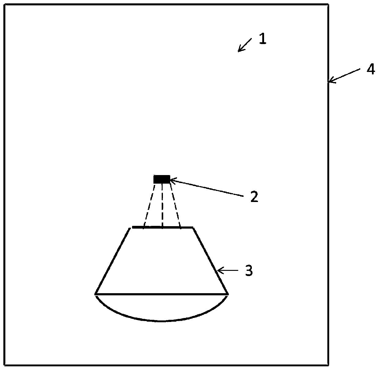
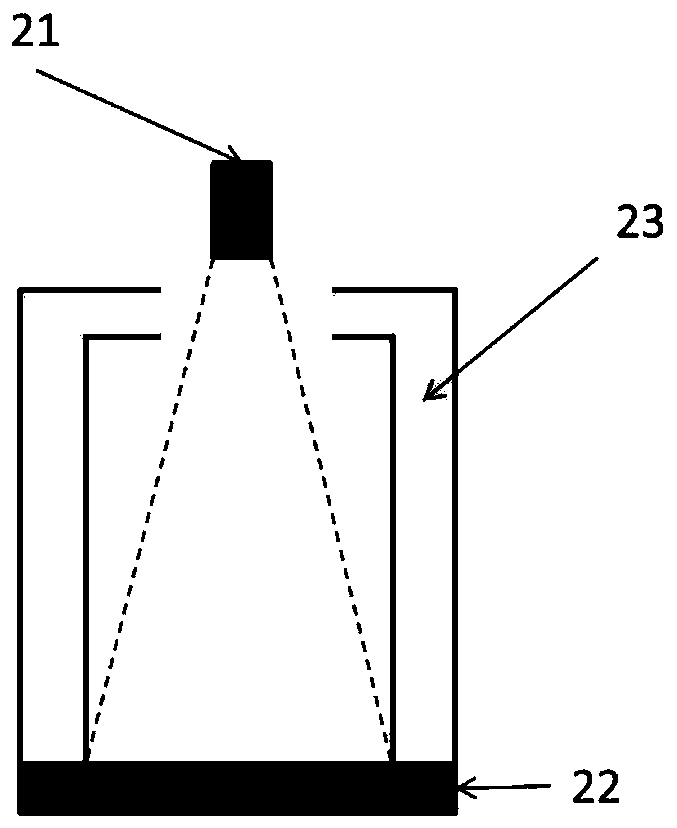
[0034] refer to figure 2 , the device of the present invention is facing the nozzle of the electric thruster 21 and is coaxial with the thruster. In order to achieve the effect of reducing sputtering pollution, the larger the target surface and the farther away from the thruster, the better, but the space left for the thruster sputtering target during the whole star test is limited, so a suitable distance must be determined first. Assuming that the distance between the center of the main target and the center of the thruster nozzle is d, in the case of vertical incidence of particles, ...


PUM


Abstract

The invention discloses a sputtering target device for reducing the plume sputtering pollution of an electric thruster during the system-level ignition test on a spacecraft powered on by the electric thruster. The device structurally comprises two parts, namely a sputtering main target and a shielding cover. The main target is directly facing the nozzle of the thruster. The material of the main target is composed of the low-sputtering-rate material graphite. The back of the main target is provided with a pipeline system. The pipeline system is in close contact with the main target, so that the pipeline system is used for cooling the main target through the cooling liquid. The pipeline system is also used for heating the main target through the hot water. The shielding cover is arranged on the main target and is used for guiding and capturing sputtering product particles, reducing the escaping probability of the sputtering product particles, and lowering the sputtering pollution. Meanwhile, the requirement of the vacuum degree is considered. The surface material of the shielding cover adopts the same material as the main target, so that the good avidity of sputtered product particles is guaranteed. The capture of sputtering products is facilitated. The device can be used for the system-level ignition test on the spacecraft powered on by the electric thruster, and serves as a plume sputtering protection means.

Description

technical field [0001] The invention relates to a device for reducing plume sputtering pollution in a system-level (whole star) ignition test of an electric propulsion spacecraft, and the sputtering pollution is controlled at a lower level through a specially designed sputtering target structure. Background technique [0002] Compared with chemical propulsion, electric propulsion can significantly reduce launch mass and increase payload and satellite in-orbit lifetime. However, when the verification test is carried out on the ground, due to the limited volume of the vacuum test chamber, the plasma plume of the electric thruster hits the wall of the container, resulting in sputtering pollution. If the sputtered particles hit the test piece, it will cause surface damage Corrosion, contamination deposits or more serious damage. [0003] The farther the sputtering surface is from the thruster, the less the sputtering pollution. Therefore, the stand-alone test of the electric th...

Claims


Application Information

Patent Timeline
Patent Type & Authority Patents(China)
IPC IPC(8): G01M15/14
CPCG01M15/14
Inventor 林博颖冯尧李培印王洪兴刘春杜春林许忠旭关来水李天水
Owner BEIJING INST OF SPACECRAFT ENVIRONMENT ENG
Learn More