
Sputtering Contamination Protection System and Design Method for Electric Thruster Ignition Test

A technology of ignition test and electric thruster, which is applied in the testing of machines/structural components, instruments, engines, etc., can solve the problems of low sputtering rate and achieve the effect of reducing sputtering pollution

Active Publication Date: 2021-07-30
BEIJING INST OF SPACECRAFT ENVIRONMENT ENG
View PDF0 Cites 0 Cited by
  • Summary
  • Abstract
  • Description
  • Claims
  • Application Information

AI Technical Summary

Problems solved by technology

The sputtering target is made of materials with low sputtering rate and has various structural forms, but due to the diffuse emission properties of sputtering products, none of the structural forms has a particularly obvious sputtering pollution protection effect

Method used


Image

  • Sputtering Contamination Protection System and Design Method for Electric Thruster Ignition Test
  • Sputtering Contamination Protection System and Design Method for Electric Thruster Ignition Test
  • Sputtering Contamination Protection System and Design Method for Electric Thruster Ignition Test

Examples


Embodiment Construction

[0037] The application will be further described in detail below in conjunction with the accompanying drawings and embodiments. It should be understood that the specific embodiments described here are only used to explain related inventions, rather than to limit the invention. It should also be noted that, for ease of description, only parts related to the invention are shown in the drawings.

[0038] It should be noted that, in the case of no conflict, the embodiments in the present application and the features in the embodiments can be combined with each other. The present application will be described in detail below with reference to the accompanying drawings and embodiments.

[0039] As mentioned in the background technology, the existing sputtering pollution protection scheme mainly starts from two aspects. One is to use the largest possible test container, because the farther the sputtering surface is from the thruster, the less pollution will be; the other is to set t...


PUM


Abstract

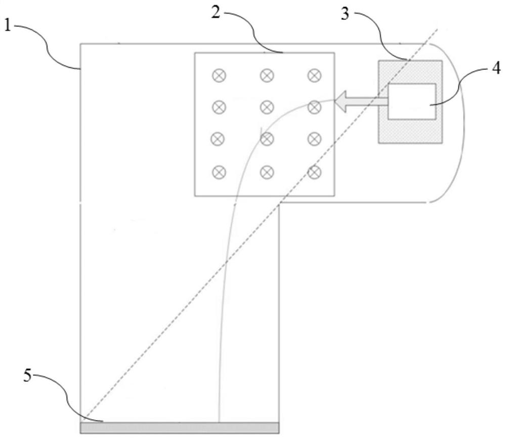
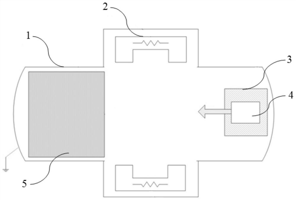
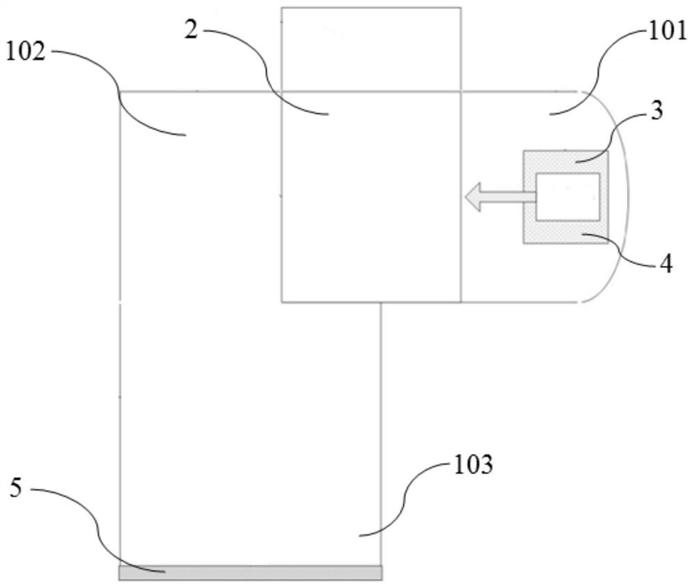
This application discloses a sputtering pollution protection system and design method for the ignition test of an electric thruster. The protection system includes an L-shaped test container, a magnetic field generator, a magnetic shield and a sputtering target. The L-shaped test container includes sequentially connected first A cavity, a transition cavity and a second cavity, the first cavity and the second cavity are perpendicular to each other; the thruster is arranged at the free end of the first cavity, and the magnetic shield is covered by the thruster In addition, the sputtering target is set at the free end of the second section cavity, and the magnetic field generator is set in the transition section cavity; the thruster generates plume particles, and the plume particles pass through the magnetic field generated by the magnetic field generator in space, and the direction of the magnetic field is Perpendicular to the movement direction of the plume particles, the strength of the magnetic field makes the particles deflect 90° and hit the sputtering target, so the pollutants generated by the sputtering of the plume particles will not directly return to the thruster, thereby reducing the thrust Sputter contamination of the device.

Description

technical field [0001] The invention generally relates to a protection device for reducing plume sputtering pollution in an ignition test of an electric thruster, in particular to a sputtering pollution protection system and a design method for the ignition test of an electric thruster. Background technique [0002] Compared with chemical propulsion, electric propulsion can greatly reduce the launch mass, improve the payload and satellite life in orbit. However, the energy of the plume particles is very high. When the verification test is carried out on the ground, because it is carried out in a vacuum test chamber with a limited volume, a large amount of pollutants will be sputtered out when the plume hits the wall of the container. These sputtered products return to the thruster or hit the Other sensitive instrument surfaces can cause contamination deposits or worse damage. [0003] The existing sputtering pollution protection scheme mainly starts from two aspects. One is...

Claims


Application Information

Patent Timeline
Patent Type & Authority Patents(China)
IPC IPC(8): G01M15/02G01M15/14
CPCG01M15/02G01M15/14
Inventor 林博颖刘春李培印冯尧许忠旭杜春林王晶
Owner BEIJING INST OF SPACECRAFT ENVIRONMENT ENG
Learn More