
Precision target system for near field target calibration of camera with large field of view and method

A large field of view and camera technology, applied in image data processing, instruments, calculations, etc., can solve problems such as low accuracy, low efficiency, and high power consumption

Inactive Publication Date: 2017-11-07
西安应用光学研究所
View PDF9 Cites 5 Cited by
  • Summary
  • Abstract
  • Description
  • Claims
  • Application Information

AI Technical Summary

Problems solved by technology

[0004] Aiming at the problems of low precision and efficiency and high power consumption of the traditional near-field calibration method for large-field cameras, the present invention provides a precision target system and method for near-field calibration of large-field cameras, relying on the multi-axis high-speed The precision numerical control system can accurately calibrate different fields of view of the camera under test with small targets, which not only effectively improves the calibration accuracy and efficiency, but also reduces system power consumption

Method used


Image

  • Precision target system for near field target calibration of camera with large field of view and method
  • Precision target system for near field target calibration of camera with large field of view and method
  • Precision target system for near field target calibration of camera with large field of view and method

Examples


Embodiment Construction

[0028] The specific implementation manner of the present invention will be described in further detail below in conjunction with the accompanying drawings.

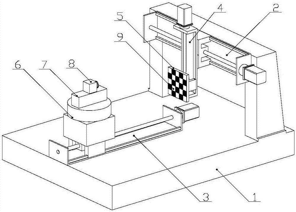
[0029] figure 1 It is a three-dimensional diagram of the precision target system for the near-field calibration of the large field of view camera in this embodiment, including the gantry frame 1, the X-axis motion mechanism 2, the Y-axis motion mechanism 3, the Z-axis motion mechanism 4, the target 5, the turntable 6, Pitch platform 7, camera under test 8, target surface 9.

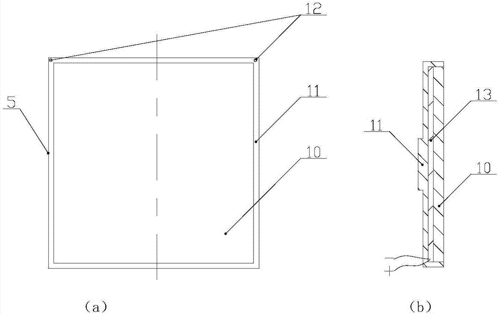
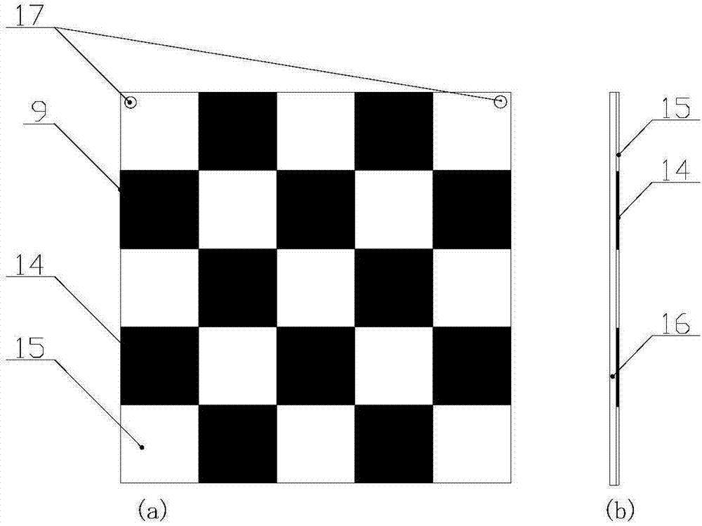
[0030] Among them, the system adopts the gantry frame 1 as the main support, and the base of the gantry frame 1 adopts shock-isolation treatment; the X-axis motion mechanism 2, the Y-axis motion mechanism 3 and the Z-axis motion mechanism 4 adopt high-precision linear motion screw shafts, and two-by-two perpendicular to each other. The target surface 9 is installed on the front of the target 5 , and the gap between them is filled with thermal condu...


PUM


Abstract

The invention discloses a precision target system for near field target calibration of a camera with a large field of view and a method. The precision target system comprises a base with a gantry frame, an X-axis motion mechanism, a Y-axis motion mechanism, a Z-axis motion mechanism, a target, a target surface, a turntable, a pitching table and a camera under test, and is characterized in that the X-axis motion mechanism, the Y-axis motion mechanism and the Z-axis motion mechanism are arranged on the base; the whole Z-axis is driven by an X-axis to move transversely; the target is fixed on the Z-axis to achieve vertical movement, and the target surface is mounted on the front of the target; the turntable is mounted on a Y-axis to achieve movement along the Y-direction; the pitching table is fixed on the table surface of the turntable; and the camera under test is fixed on the table surface of the pitching table. When the precision target system is in operation, an appropriate target surface is mounted, and the system is powered; the camera is enabled to directly faces the target surface by a certain distance through adjusting the components, then the turntable, the pitching table and the Y-axis are fixed; and the position of the target surface is adjusted through the X-axis and the Z-axis, and calibration for different fields of view of the camera under test is realized. The precision target system realizes near-field target calibration for a camera with two wavebands and various large fields of view through combining the small-size precision target and the multi-axis precision numerical control system, and improves the target calibration efficiency.

Description

technical field [0001] The invention relates to the field of precision optical imaging, in particular to an optical imaging camera calibration system, in particular to a precision target system and method for near-field calibration of a large field of view camera. Background technique [0002] With the development of society and the advancement of science and technology, more and more cameras are used in various fields of military and civilian use; and according to the improvement of practical application requirements, the requirements for camera imaging quality are also getting higher and higher, so the calibration camera The target application of imaging distortion is also becoming more and more extensive. High-precision optical target is an indispensable calibration instrument in the technical fields of optical measurement, optical imaging, visual measurement and robot vision. It is based on the imaging detection of known geometric quantities on the optical target to cali...

Claims


Application Information

Patent Timeline
IPC IPC(8): G06T7/80
CPCG06T7/80
Inventor 王谭王磊磊郭冰涛侯军占张卫国段红建宁新潮李世尧
Owner 西安应用光学研究所
Learn More