
Device and method for measuring viscosity of fluid near-critical area

A near-critical and fluid technology, applied in the direction of measuring devices, indirect flow characteristic measurement, flow characteristics, etc., can solve problems such as poor reproducibility, low accuracy, and inability to carry out measurements

Active Publication Date: 2017-11-07
XI AN JIAOTONG UNIV
View PDF5 Cites 5 Cited by
  • Summary
  • Abstract
  • Description
  • Claims
  • Application Information

AI Technical Summary

Problems solved by technology

The core problem leading to its limitations is that the experimental principles of the above-mentioned measurement methods are all based on the physical-mathematical model describing the macroscopic transfer process (such as the pipeline laminar flow model in the capillary viscometry method), and the use of the above-mentioned method to carry out viscosity measurement The first technical link is to establish a certain potential difference with the help of corresponding devices to form and maintain a stable and measurable macroscopic momentum transfer gradient
However, when the thermodynamic state of the fluid is in its near-critical region, the viscosity exhibits extraordinary changes under the action of density fluctuations, making it possible to establish a stable and measurable macromomentum transfer gradient and keep the thermodynamic state of the fluid to be measured consistent (thermophysical property measurement basic requirements) has become a pair of irreconcilable contradictions
This core problem leads to poor reproducibility and low accuracy of the viscosity experimental results measured by the above methods when they are close to the critical point of the fluid to be tested, and even the measurement cannot be carried out.

Method used


Image

  • Device and method for measuring viscosity of fluid near-critical area
  • Device and method for measuring viscosity of fluid near-critical area
  • Device and method for measuring viscosity of fluid near-critical area

Examples


Embodiment Construction

[0071] The present invention will be further described in detail below in conjunction with specific embodiments, which are explanations of the present invention rather than limitations.

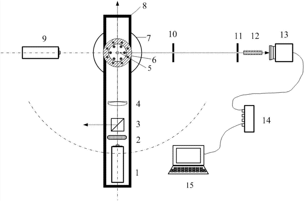
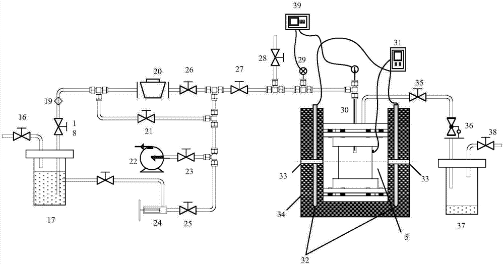
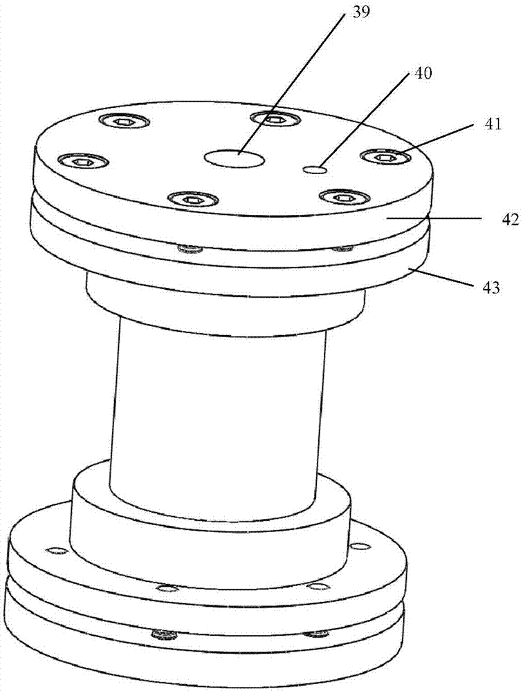
[0072] see figure 1 , the device suitable for measuring the viscosity of fluid in the near-critical region of the present invention includes a polarization optical path, an experimental unit, a scattering optical path and a detection and analysis unit. The experimental unit has a light-transmitting experimental body 5 and a temperature and pressure control system, and the internal energy of the experimental body 5 is The fluid to be measured is filled; the temperature and pressure control system is used to control the temperature and pressure of the fluid to be measured; the polarized light of the polarized light path enters the experimental body 5 to generate scattered light, and the scattered light is detected and analyzed by the detection and analysis unit through the scattered light path. ...


PUM


Abstract

The invention provides a device and a method for measuring viscosity of a fluid near-critical area. The device comprises a polarized light path, an experiment unit, a diffracted light path and a detection and analyzing unit, wherein the laser emitted by a laser device can be subject to attention by an adjustable attenuation sheet, polarizing and light dividing by a polarizing and light dividing prism, gathering by a lens, and transmitting into an experiment body; the diffracted light produced by the experiment unit passes through a light diaphragm and a light shielding cylinder, and is detected by a photo counter, and the detecting result is transmitted to an analyzer by a digital correlator; the analyzer is used for calculating to obtain the viscosity of the near-critical area of the to-be-measured fluid according to the detecting result; the experiment unit comprises the experiment body and a temperature and pressure control system, the experiment body is used for carrying the to-be-measured fluid, and the temperature and pressure control system is used for enabling the to-be-measured fluid to reach the temperature and pressure of the near-critical area; an electric heater and a temperature controller are used for controlling the temperature of the to-be-measured fluid, the to-be-measured fluid is pressurized and pumped into the device for controlling the pressure of the to-be-measured fluid, and a measuring circuit is used for detecting the pressure and temperature of the to-be-measured fluid.

Description

technical field [0001] The invention belongs to the technical field of measuring fluid thermophysical properties, and relates to a device and a method suitable for measuring the viscosity of a fluid near a critical region. Background technique [0002] Viscosity is a property of fluid resistance to shear deformation. It is one of the main thermophysical parameters of fluid. Viscosity and its measurement involve many fields of scientific research and engineering practice. Viscosity measurement is an important means to control the production process, ensure safe production, control and evaluate product quality, and scientific research. It is widely used in many fields such as petroleum, chemical industry, medicine, transportation, metallurgy, and aerospace. [0003] Conventional methods of viscosity measurement mainly include: capillary method, falling ball method, rotation method and vibration method. The capillary method is the most widely used viscosity measurement method,...

Claims


Application Information

Patent Timeline
Patent Type & Authority Applications(China)
IPC IPC(8): G01N11/00
CPCG01N11/00G01N2011/008
Inventor 张颖何茂刚刘向阳郑宇
Owner XI AN JIAOTONG UNIV
Learn More