Eureka AIR delivers breakthrough ideas for toughest innovation challenges, trusted by R&D personnel around the world.

Textile machine supporting device

A technology for supporting devices and textile machinery, applied in the direction of lifting devices, mechanical equipment, supporting machines, etc., can solve the problems of affecting the working efficiency of textile machinery, affecting the work of textile machinery, and being unable to adjust the height, etc., to solve the problem of inconvenient movement and simple structure , to avoid the effect of offset

Inactive Publication Date: 2017-11-07
黄忠南
View PDF0 Cites 61 Cited by
  • Summary
  • Abstract
  • Description
  • Claims
  • Application Information

AI Technical Summary

Problems solved by technology

[0002] Textile machinery plays an indispensable and important role in the textile industry, and the supporting device of textile machinery is a foundation of textile machinery. Whether the supporting device of textile machinery is good or not determines the working efficiency of a textile machinery support. The height of the device is fixed, and it cannot be adjusted to the most suitable height for different users, which will undoubtedly affect the working efficiency of textile machinery
[0003] In addition, the existing supporting devices for textile machinery have poor shock absorption. During transportation or operation, different degrees of vibration and impact will be generated, which may easily cause damage to the textile machinery. Moreover, the position of the textile machinery can only be fixed, and it is inconvenient to move. , which undoubtedly affects the work of textile machinery and brings inconvenience to users

Method used

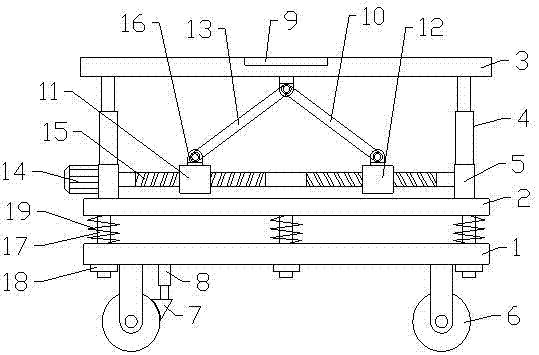

Image

  • Textile machine supporting device
  • Textile machine supporting device
  • Textile machine supporting device

Examples


Embodiment Construction

[0018] The following will clearly and completely describe the technical solutions in the embodiments of the present invention with reference to the accompanying drawings in the embodiments of the present invention. Obviously, the described embodiments are only some, not all, embodiments of the present invention. Based on the embodiments of the present invention, all other embodiments obtained by persons of ordinary skill in the art without making creative efforts belong to the protection scope of the present invention.

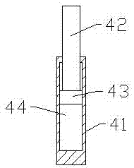
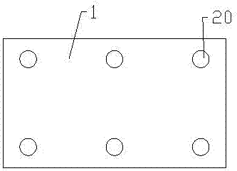
[0019] see Figure 1-3 , in an embodiment of the present invention, a textile machinery support device includes a support base 1, a support plate 2, a workbench 3, a support sleeve rod 4, a No. 1 connecting rod 10, a No. 2 slider 11, a No. 1 slider 12, No. 2 connecting rod 13, hinged seat 16 and damping spring 19, said support base 1 is provided with six guide sliding holes 20 symmetrically, and all slide in each guiding sliding hole 20 and be provided with gu...


PUM


Abstract

The invention discloses a textile machinery supporting device, which comprises a supporting base, a supporting plate, a workbench, a supporting sleeve rod, a No. 1 connecting rod, a No. 2 sliding block, a No. 1 sliding block, a No. 2 connecting rod, a hinge seat and shock The upper surface of the support plate is symmetrically fixed with a support vertical plate, the rotating frame on the two support vertical plates is provided with a screw, the upper surface of the support vertical plate is symmetrically fixed with a support sleeve rod, and the workbench is fixed on the support sleeve rod. At the top, the No. 2 slider is set on the outer ring of the left end of the lead screw by thread connection, the No. 1 slider is set on the right end outer ring of the lead screw by thread connection, and the lower surface of the middle part of the workbench is connected to the outer ring of the No. 2 slider. The upper surfaces are connected through the No. 2 connecting rod, and the middle lower surface of the workbench is connected with the upper surface of the No. 1 slide block through the No. 1 connecting rod. The invention can adjust the height according to the use requirements of the textile machine, and at the same time solves the problems of inconvenient movement, poor shock absorption and the like.

Description

technical field [0001] The invention relates to the technical field of textile machinery, in particular to a textile machinery supporting device. Background technique [0002] Textile machinery plays an indispensable and important role in the textile industry, and the supporting device of textile machinery is a foundation of textile machinery. Whether the supporting device of textile machinery is good or not determines the working efficiency of a textile machinery support. The height of the device is fixed, and it cannot be adjusted to the most suitable height for different users, which will undoubtedly affect the working efficiency of the textile machinery. [0003] In addition, the existing supporting devices for textile machinery have poor shock absorption. During transportation or operation, different degrees of vibration and impact will be generated, which may easily cause damage to the textile machinery. Moreover, the position of the textile machinery can only be fixed...

Claims


Application Information

Patent Timeline
IPC IPC(8): F16M3/00B66F7/06F16F15/04
CPCF16M3/00B66F7/0608B66F7/0625B66F7/0633F16F15/04
Inventor 黄忠南
Owner 黄忠南
Why Eureka
Eureka Blog
Learn More