Bearing column and cantilever device

A technology of a column and a bearing part, which is applied to the field of bearing columns and cantilever devices, can solve the problems of increased horizontal operating force, large hindering effect of the rotating shaft, low operating efficiency, etc., so as to reduce the horizontal operating force, improve the operating efficiency, and reduce the movement obstruction. Effect

Active Publication Date: 2018-08-31
SHENZHEN LONGHAITE ROBOT TECH CO LTD
View PDF5 Cites 0 Cited by
  • Summary
  • Abstract
  • Description
  • Claims
  • Application Information

AI Technical Summary

Problems solved by technology

[0005] In the traditional column structure, due to the limitation of the structure, the hindrance to the rotation axis is too large, which often requires a large horizontal operating force and low operating efficiency
Especially under the gravity of the load, the cantilever will sag under pressure and drift, which will aggravate the obstruction of the column to the movement of the rotation axis, and further increase the required horizontal operating force

Method used


Image

  • Bearing column and cantilever device
  • Bearing column and cantilever device
  • Bearing column and cantilever device

Examples


Embodiment 1

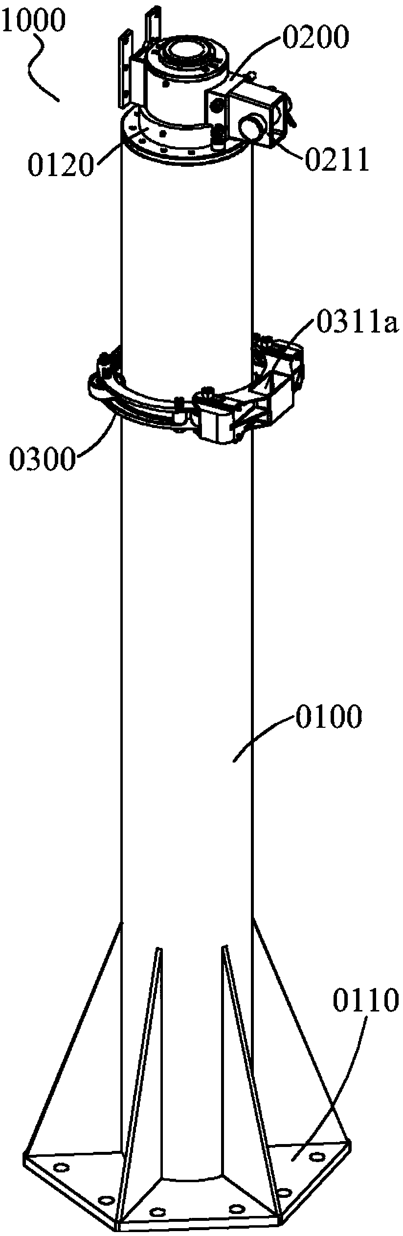
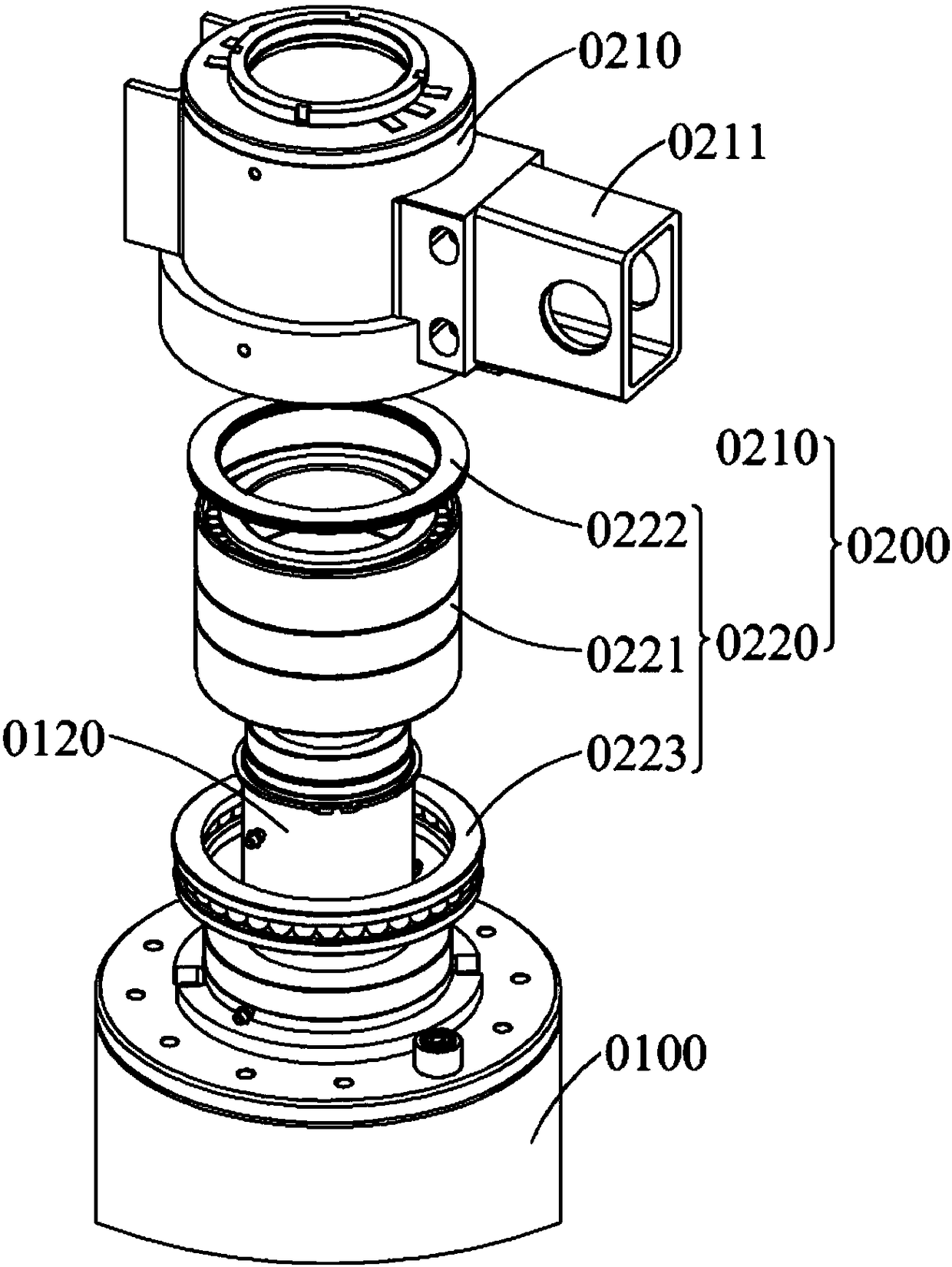
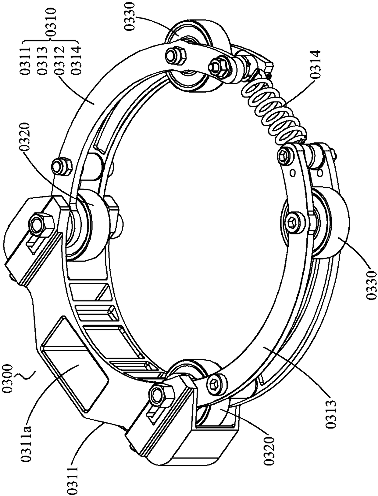
[0040] see figure 1 The supporting column 1000 has a column body 0100, a rotating shaft part 0200 and a bearing part 0300, which can bear the rotational load during the cantilever rotation process, overcome the impact caused by the torque change of the cantilever, and ensure the cantilever to rotate smoothly in the horizontal direction. The specific structure of each part of the supporting column 1000 will be introduced one by one below.

[0041]As a supporting base for supporting the column 1000, the column body 0100 is arranged along the vertical direction. The column body 0100 should have sufficient structural strength and rigidity, and can adopt various structural forms, such as tubular structure, solid column, etc. The column body 0100 can also adopt various shapes, such as square column, cylinder, hexagonal column and so on. The column body 0100 has at least one cylindrical surface between the upper and lower ends, and the central axis of the cylindrical surface coinci...


PUM


Abstract

A bearing column comprises a column body (0100), a rotary shaft portion (0200), and a bearing portion (0300). Two ends of the column body (0100) are respectively provided with a bottom support portion (0110) and a rotary shaft support portion (0120). The rotary shaft portion (0200) is rotatably maintained on the rotary shaft support portion (0120) and has a first connecting portion (0211) fixedly connected to a cantilever. The bearing portion (0300) comprises a rotary frame (0310). The rotary frame (0310) is coaxial with the rotary shaft portion (0200), maintained on the column body (0100), and rotates in synchronization with the rotary shaft portion (0200). The rotary shaft portion (0200) has a second connecting portion (0311a) fixedly connected to the cantilever. The second connecting portion (0311a) is symmetrically provided with at least one first rolling portion (0320) at each of two sides of the rotary frame (0310) in a rotation direction thereof. At least one second rolling portion (0330) is provided between the outermost pair of first rolling portions (0320). The first rolling portion (0320) and the second rolling portion (0330) are rotatably maintained on the rotary frame (0310), and are in rolling contact with the column body (0100).

Description

technical field [0001] The invention belongs to the technical field of hoisting machinery, in particular to a bearing column and a cantilever device. Background technique [0002] The column is a common component in the field of hoisting machinery, which is erected vertically on the ground or on the frame to provide support for other components connected to the column. Generally, the column needs to have sufficient rigidity to ensure sufficient bearing capacity. [0003] Where the supported part has rotational motion, such as in a self-erecting jib crane, the column needs to bear both the load force and the torque. Generally, the rotatable supported part is a cantilever, which rotates around a rotation axis provided on the column under the push of a horizontal operating force. Among them, the horizontal operating force is an important index to examine the operating comfort and efficiency. [0004] The horizontal operating force is used to overcome the resistance and block...

Claims


Application Information

Patent Timeline
Patent Type & Authority Patents(China)
IPC IPC(8): B66C23/62B66C23/68B66C23/70
CPCB66C23/62B66C23/68B66C23/70B66C2700/03
Inventor 蔡昌荣蒋振宇李满天邓静李爱镇王鑫刘国才刘建伟史亚鹏
Owner SHENZHEN LONGHAITE ROBOT TECH CO LTD
Why Eureka
Try Eureka