
Pneumatic paste filling machine

A filling machine and paste technology, applied in packaging, liquid materials, packaging protection, etc., can solve the problems of no feeding, difficult movement, easy damage or loss, etc., to prevent paste precipitation or condensation, and improve product quality , the effect of preventing material breaking

Inactive Publication Date: 2017-11-07
FOSHAN HANGESI ENVIRONMENTAL PROTECTION TECH CO LTD
View PDF7 Cites 3 Cited by
  • Summary
  • Abstract
  • Description
  • Claims
  • Application Information

AI Technical Summary

Problems solved by technology

[0002] Pneumatic paste filling machine uses compressed air as power, and is composed of precision pneumatic components to form an automatic filling system. It has simple structure, sensitive and reliable action, and convenient adjustment. Working in flammable and explosive environments, it is the most ideal filling equipment for pharmaceutical, chemical, food, cosmetics and other industries. The existing pneumatic paste filling machines are relatively large in size and difficult to move. The paste in the storage hopper When it is not in cans for a period of time, precipitation or condensation will occur, which will affect product quality. The foot switch has no good storage space after use, and it is easy to be damaged or lost. Generally, there is no special person to monitor the storage hopper, and it is easy to cause paste The situation of using up without feeding will affect the filling efficiency

Method used


Image

  • Pneumatic paste filling machine
  • Pneumatic paste filling machine
  • Pneumatic paste filling machine

Examples


Embodiment Construction

[0021] The preferred embodiments of the present invention will be described below in conjunction with the accompanying drawings. It should be understood that the preferred embodiments described here are only used to illustrate and explain the present invention, and are not intended to limit the present invention.

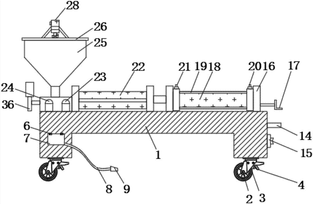
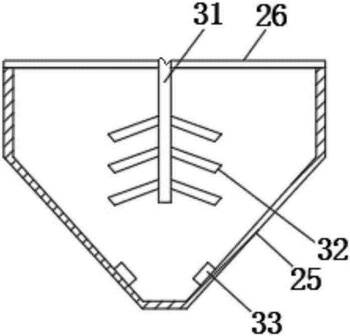
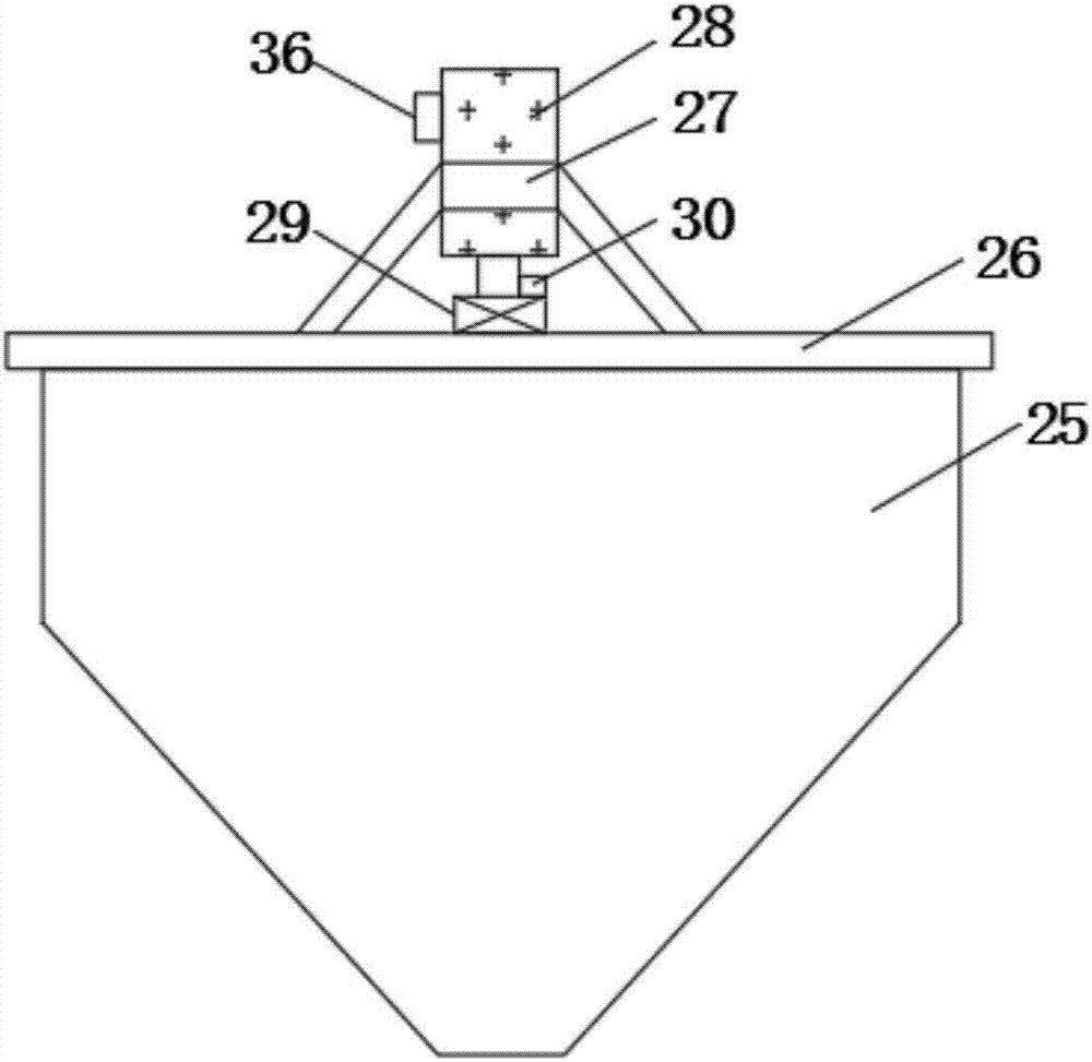
[0022] see Figure 1-5 , the present invention provides a technical solution: a pneumatic paste filling machine, including a base 1, a fixed shaft 2, a pulley 3, a brake lever 4, a storage slot 5, a first hinge 6, a sealing cover 7, and a wire 8 , foot switch 9, shock-absorbing bottom plate 10, shock-absorbing top plate 11, spring limit post 12, shock-absorbing spring 13, air inlet 14, power switch 15, fixed frame 16, quantitative handwheel 17, cylinder 18, fixed thread Rod 19, suction speed regulator 20, feeding speed regulator 21, metering tube 22, first alarm 23, second alarm 24, storage hopper 25, end cap 26, motor frame 27, stirring motor 28, Coupling 29, disp...


PUM


Abstract

The invention discloses a pneumatic paste filling machine. The machine comprises a base and a storage hopper; sliding wheels are mounted at the bottom of the base through fixing rotating shafts; a brake rod is mounted on one side of each sliding wheel; an accommodating groove is formed in one side of the base; a sealing cover is mounted at one end of the accommodating groove through first hinges; a power switch is mounted on one side of an air inlet; a second alarm is mounted on one side of a first alarm; the storage hopper is mounted on one side of the second alarm; a stirring motor is mounted in the middle of a motor frame; a programmable logic controller (PLC) is mounted on one side of the stirring motor; a rotating shaft is sleeved with the other side of a coupling; stirring blades are welded at the bottom of the rotating shaft; and a pressure sensor is mounted at the bottom end inside the storage hopper. The machine is convenient to move, paste sedimentation or condensation can be prevented, the product quality can be improved, a foot switch is convenient to store, the storage hopper is monitored in real time, material breakage is prevented, and the machine is convenient to use.

Description

technical field [0001] The invention relates to a sealing device for packaging film sealing, in particular to a pneumatic paste filling machine. Background technique [0002] Pneumatic paste filling machine uses compressed air as power, and is composed of precision pneumatic components to form an automatic filling system. It has simple structure, sensitive and reliable action, and convenient adjustment. Working in flammable and explosive environments, it is the most ideal filling equipment for pharmaceutical, chemical, food, cosmetics and other industries. The existing pneumatic paste filling machines are relatively large in size and difficult to move. The paste in the storage hopper is When not in cans for a period of time, precipitation or condensation will occur, which will affect product quality. The foot switch has no good storage space after use, and it is easy to be damaged or lost. Generally, there is no special person to monitor the storage hopper, which is easy to ...

Claims


Application Information

Patent Timeline
Patent Type & Authority Applications(China)
IPC IPC(8): B65B3/00B65B57/18B65B3/14
CPCB65B3/00B65B3/14B65B57/18
Inventor 田容宋兆东
Owner FOSHAN HANGESI ENVIRONMENTAL PROTECTION TECH CO LTD
Learn More