
A remote control aircraft without a rotor

An aircraft and rotor technology, which is applied in the field of small remote control toy aircraft, can solve problems such as the influence of aircraft stability, and achieve the effects of improving flight stability, simple and convenient control, and reducing airflow turbulence.

Active Publication Date: 2019-11-01
CHANGZHOU INST OF TECH
View PDF6 Cites 0 Cited by
  • Summary
  • Abstract
  • Description
  • Claims
  • Application Information

AI Technical Summary

Problems solved by technology

[0006] Second, it uses the steering device to control the angle of the annular air outlet device to realize aircraft rotation and other actions, and to control the rotation of the annular air outlet device to change the wind outlet angle also needs to carry out movable joint connection to the annular air outlet device, and the setting of the steering device Increased the structural complexity of the aircraft, which has a great impact on the stability of the aircraft;
[0007] Third, its total suction booster device uses a power drive device to drive the impeller to achieve air boosting. For remote-controlled aircraft, jet stability is crucial, and there are rarely rotorless jet drones on the market. The key reason is that the jet lift stability of the rotorless jet UAV is higher than that of the rotor UAV, and there is a big gap, so the air pressure uniformity and stability of the rotorless jet UAV need to be further improved

Method used


Image

  • A remote control aircraft without a rotor
  • A remote control aircraft without a rotor
  • A remote control aircraft without a rotor

Examples


Embodiment

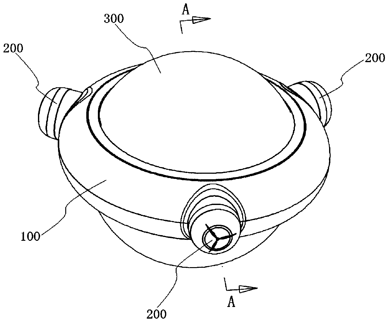
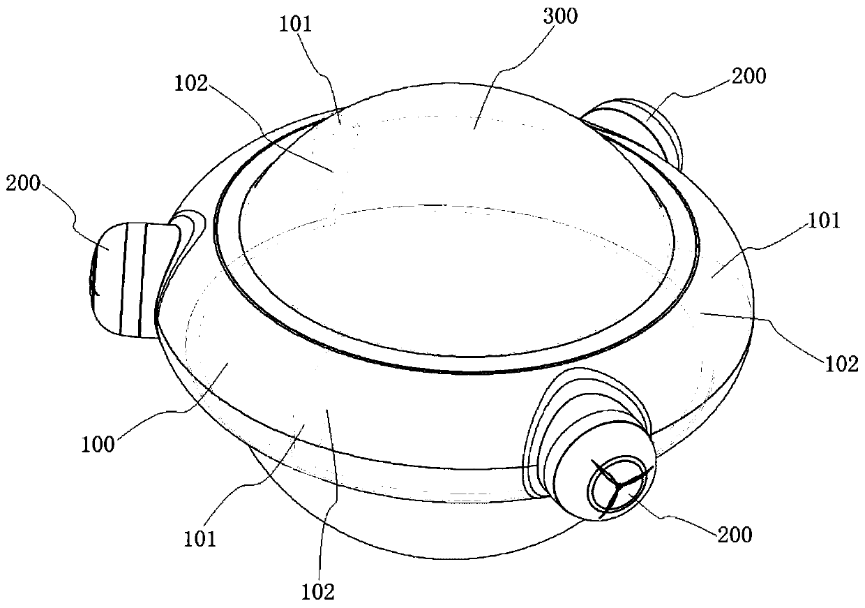
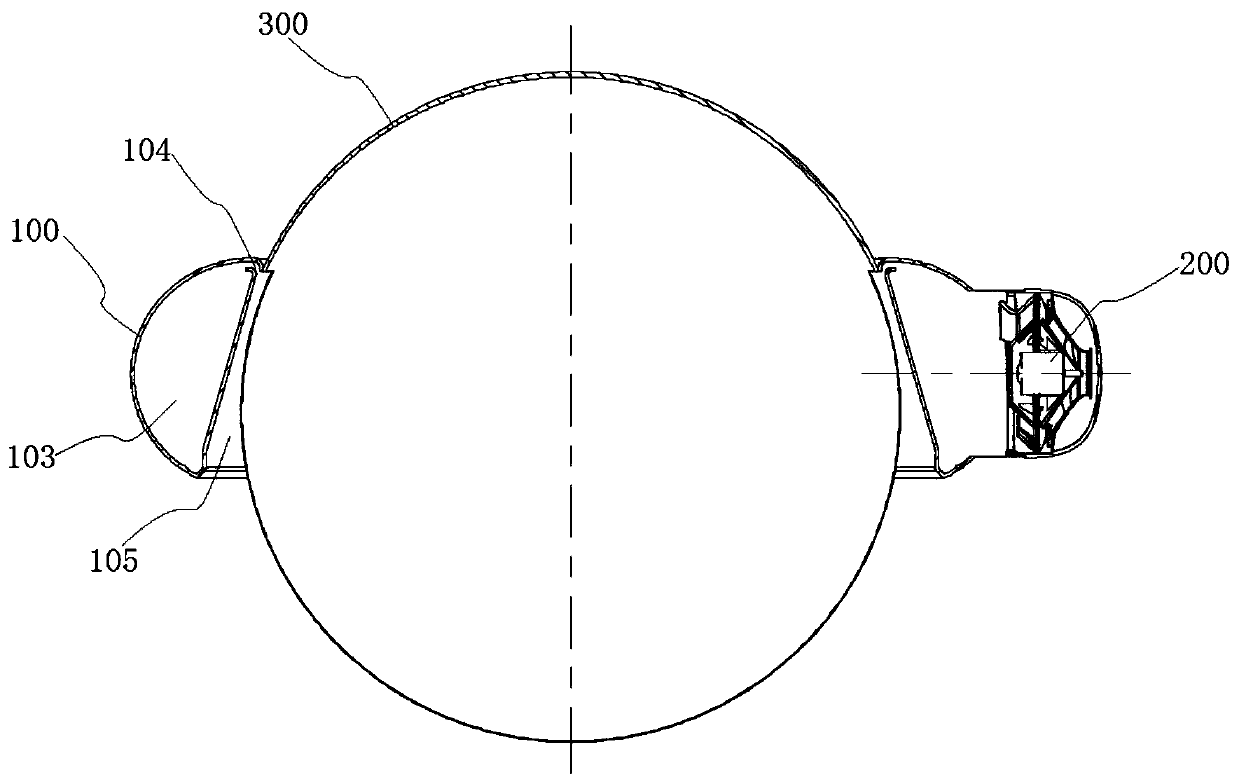
[0042] combine figure 1 , figure 2 and image 3 As shown, a kind of non-rotor remote control aircraft of the present embodiment comprises annular blowing cavity 100, turbo blowing mechanism 200 and bin body 300, and bin body 300 is fixed in the middle of annular blasting cavity 100, can be in the bin body 300 Parts such as the controller, power supply and indicator lights of the aircraft are installed, parts such as the floor stand and the camera installation bracket can also be set at the bottom of the warehouse body 300; There are at least three groups of partitions 101 that equally divide the annular cavity 103 into mutually independent areas, such as figure 2 As shown, three partitions 101 are used to divide the annular cavity 103 into three groups of independent areas, and the middle of each independent area of ​​the annular cavity 103 is correspondingly evenly arranged on the outer wall of the annular blast cavity 100. A turbo blower mechanism 200 for blowing air in...


PUM


Abstract

The invention discloses a rotorless remote-controlled aircraft, which belongs to the field of jet aircraft. The rotorless remote control aircraft of the present invention comprises an annular blast cavity, a turbine blow mechanism and a bin body, the bin body is fixed in the middle of the annular blast cavity, an annular cavity is arranged in the annular blast cavity, and an annular cavity is arranged in the annular cavity. There are at least three sets of partitions that equally divide the annular cavity into mutually independent areas, and the middle part of each independent area of ​​the annular cavity is correspondingly provided with a set of evenly arranged on the outer wall of the annular blast cavity for blowing the air to the annular A turbine blowing mechanism that blows air into the cavity. The annular blowing cavity is provided with a circle of air jets that can jet downward to provide lift. The annular cavity is also equipped with a steering mechanism that can drive the diaphragm to rotate to change the direction of the jet. . The aircraft of the present invention has simple and compact structure, strong flight power, stable and reliable flight, simple and convenient control, and strong battery life; at the same time, the aircraft is safer to use and meets the needs of young children.

Description

technical field [0001] The invention relates to a remote-controlled unmanned aerial vehicle, more specifically, to a non-rotor remote-controlled aerial vehicle, in particular to a small remote-controlled toy aerial vehicle suitable for children. Background technique [0002] Unmanned aircraft is referred to as "UAV (Unmanned Aerial Vehicle)", and the English abbreviation is "UAV". operate autonomously. [0003] At present, there are many types of aircraft on the market, and most of them are multi-rotor aircraft, which are mainly aimed at adults. They have excellent maneuverability and can take off and land vertically without a runway. In terms of reliability, the multi-rotor is also the best performer. Existing multi-rotor drones are noisy, and their propeller rotors have poor drop resistance. Encountering debris and branches during flight may directly cause the propeller to be scrapped, and it has problems such as high energy consumption and short battery life. In additi...

Claims


Application Information

Patent Timeline
Patent Type & Authority Patents(China)
IPC IPC(8): B64C39/02
CPCB64C39/024B64U10/13B64U50/19
Inventor 毛建秋刘珂琴周文聪周正旺
Owner CHANGZHOU INST OF TECH
Learn More