A sheet metal punching positioning and fixing device
What is Al technical title?
Al technical title is built by PatSnap Al team. It summarizes the technical point description of the patent document.
A fixing device and punching technology, which is applied in the field of sheet metal punching positioning and fixing devices, can solve the problems of unfixed processing materials, unguaranteed processing accuracy, hidden safety hazards, etc., and achieve the effect of preventing displacement, protecting processing accuracy and processing quality
Inactive Publication Date: 2019-04-02
柳州易晟模具有限公司
View PDF8 Cites 2 Cited by
Summary
Abstract
Description
Claims
Application Information
AI Technical Summary
This helps you quickly interpret patents by identifying the three key elements:
Problems solved by technology
Method used
Benefits of technology
Problems solved by technology
[0003] Aiming at the deficiencies of the prior art, the present invention provides a sheet metal punching positioning and fixing device, which solves the problem that the existing sheet metal punching equipment does not have specific processing equipment, and basically directly punches holes with manual operation. The processing accuracy cannot be guaranteed, and it is easy to damage the product. At the same time, there is no protective device during processing, which may easily cause safety hazards. The processing materials are not fixed, which may easily lead to deviations, waste materials, and reduce product quality.
Method used
Image
Click on the blue label to locate the original text in one second.
Reading with bidirectional positioning of images and text.
Examples
Embodiment Construction
[0026] The following will clearly and completely describe the technical solutions in the embodiments of the present invention with reference to the accompanying drawings in the embodiments of the present invention. Obviously, the described embodiments are only some, not all, embodiments of the present invention. Based on the embodiments of the present invention, all other embodiments obtained by persons of ordinary skill in the art without making creative efforts belong to the protection scope of the present invention.
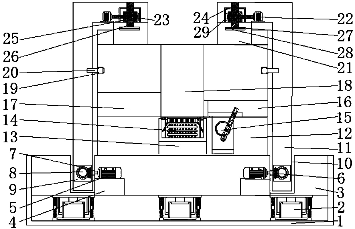
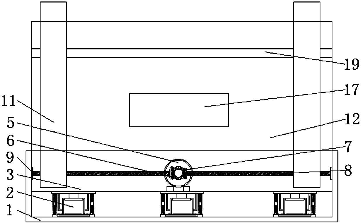
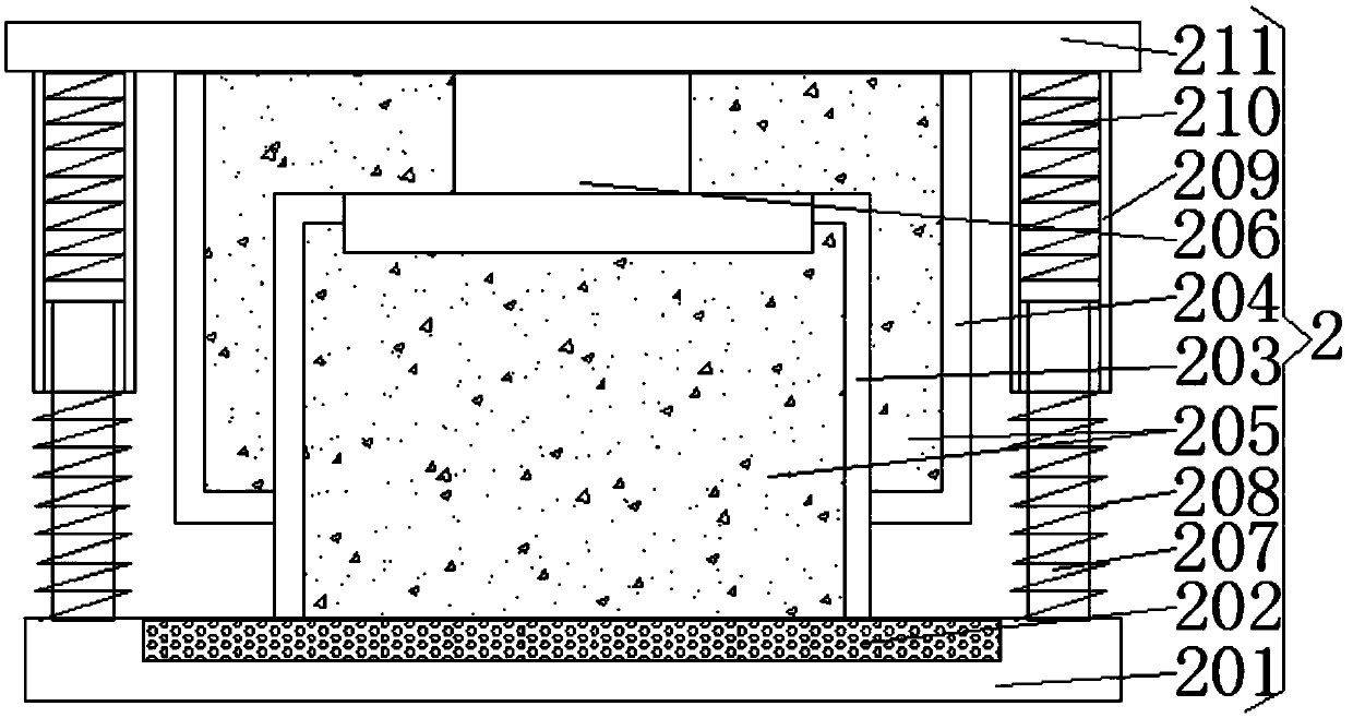
[0027] see Figure 1-5, the present invention provides a technical solution: a sheet metal punching positioning and fixing device, including a U-shaped bottom plate 1, a plurality of shock absorbing devices 2 are fixedly connected to the bottom of the inner surface of the U-shaped bottom plate 1, and the shock absorbing device 2 includes a bottom plate 201, the bottom plate The middle position of the top of 201 is fixedly connected with a rubber pad 202, and t...
PUM
Abstract
The invention discloses a punching positioning and fixing device for sheet metal. The punching positioning and fixing device comprises a U-shaped base plate; a plurality of damping devices are fixedly connected to the bottom of the inner surface of the U-shaped base plate; L-shaped fixing columns are connected to the outer surfaces of roller screws in a threaded mode; an objective table is fixedly connected to the middle position of the top of a supporting block; a buffering device is fixedly connected to the top of a fixing block; a horizontal pushing device is fixedly connected to the position, located at one side of the fixing block, at the bottom of an inner cavity of the objective table; turbine boxes are fixedly connected to one sides of the bottoms of inner cavities at the tops of the L-shaped fixing columns; and fixing plates are connected to the ends, close to the objective table, of threaded rods in a rotating mode. The invention relates to the field of sheet metal machining equipment. The punching positioning and fixing device has the advantages that a workpiece to be machined can be fastened, displacement of the workpiece can be prevented, the machining precision and the machining quality in the machining process of the workpiece can be protected, vibration can be reduced, a machine can be protected, and therefore the impact force of a punch hammer can be buffered in the punching process, the device can be protected, waste materials caused by punching can be pushed out, and the phenomenon that the machining quality is influenced due to the obstruction of the waste materials can be avoided.
Description
technical field [0001] The invention relates to the field of sheet metal processing equipment, in particular to a sheet metal punching positioning and fixing device. technical background [0002] Sheet metal has not yet had a relatively complete definition. According to a definition in a foreign professional journal, it can be defined as: sheet metal is a comprehensive cold processing process for metal sheets, including shearing, punching, cutting, compounding, folding, welding, riveting, splicing, forming, etc. Its remarkable feature is that the thickness of the same part is consistent. Sheet metal has the characteristics of light weight, high strength, electrical conductivity, low cost, and good mass production performance. It has been widely used in electronic appliances, communications, automobile industry, medical equipment and other fields, such as in computer cases, mobile phones, and MP3 , sheet metal is an essential component. With the application of sheet metal ...
Claims
Application Information
Patent Timeline
Application Date:The date an application was filed.
Publication Date:The date a patent or application was officially published.
First Publication Date:The earliest publication date of a patent with the same application number.
Issue Date:Publication date of the patent grant document.
PCT Entry Date:The Entry date of PCT National Phase.
Estimated Expiry Date:The statutory expiry date of a patent right according to the Patent Law, and it is the longest term of protection that the patent right can achieve without the termination of the patent right due to other reasons(Term extension factor has been taken into account ).
Invalid Date:Actual expiry date is based on effective date or publication date of legal transaction data of invalid patent.