Metal casting smelting and clamping integrated device

A metal casting, integrated technology, used in crucible furnaces, furnaces, charging processing types, etc., can solve the problems of uneven temperature, toxic gases and waste solids, uneven heating of metals, and achieve the effect of uniform heating

Inactive Publication Date: 2017-11-03
湖州市下昂多联铸造有限公司
View PDF0 Cites 0 Cited by
  • Summary
  • Abstract
  • Description
  • Claims
  • Application Information

AI Technical Summary

Problems solved by technology

[0002] Metal casting is the process of smelting metal into a liquid that meets certain requirements in a furnace and pouring it into a mold. After cooling, solidification, and cleaning, a casting with a predetermined shape, size, and performance is obtained. Generally, after putting the metal objects into the crucible, put them into the burning coal furnace device for heating until the metal objects in the crucible are smelted into liquid, and the coal blocks are affected by external forces such as wind when placed in the coal furnace. The temperature in the furnace is uneven, the metal is heated unevenly in the crucible, and the combustion of coal and other substances will produce toxic gases and waste solids, which will also pollute the environment; when the metal is melted in the crucible of the furnace, it needs to be taken out. In the market, it is generally used to manually clamp the crucible through the clamp, and then take the crucible to the mold. Since the clamp will be shaken artificially, the high-temperature molten metal in the crucible is easy to shake out of the crucible during the clamping process, and the stability is low. , and during the clamping process, due to the high temperature of the crucible, the high-temperature metal in the crucible is also easy to shake, and it is easy to cause danger if workers make mistakes during operation, and the safety is poor
Therefore, the existing smelting and clamping devices used in the foundry industry have the problems of uneven heating, environmental pollution, low stability and poor safety.

Method used


Image

  • Metal casting smelting and clamping integrated device
  • Metal casting smelting and clamping integrated device
  • Metal casting smelting and clamping integrated device

Examples


Embodiment Construction

[0020] The present invention will be further described below in conjunction with the accompanying drawings and embodiments, but not as a basis for limiting the present invention.

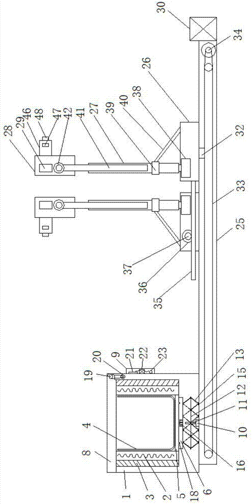
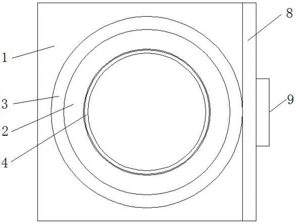
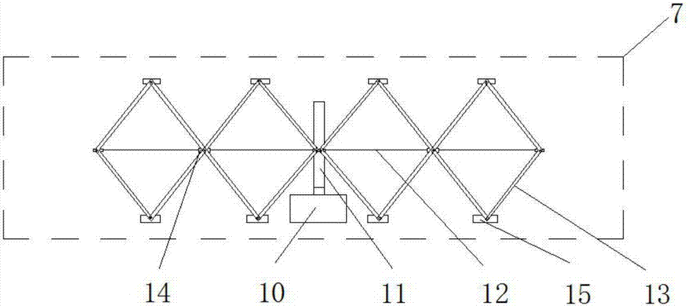
[0021] Example. An integrated device for smelting and clamping for metal casting, which is composed of Figures 1 to 8 As shown, a furnace shell 1 is included, and the inner wall of the furnace shell 1 is provided with a heating element 2, and an insulating layer 3 is connected between the inner wall of the furnace shell 1 and the heating element 2; the furnace shell 1 is provided with a crucible 4, and the bottom of the crucible 4 is connected with Furnace bottom plate 5; the bottom of the furnace bottom plate 5 is connected with a rotating plate 6, and the bottom of the rotating plate 6 is connected with a lifting device 7; the top of the furnace shell 1 is connected with a furnace cover 8, and one side of the furnace shell 1 is provided with a control system 9; the furnace The bottom of the shel...


PUM


Abstract

The invention discloses a melting and clamping integrated device for metal casting, which comprises a furnace shell (1), in which a heating element (2), an insulating layer (3) and a crucible (4) are arranged; the crucible ( 4) The bottom is provided with a furnace bottom plate (5), a rotating plate (6 and a lifting device (7) in sequence; the furnace cover (8) is connected to the top of the furnace shell (1), and a control system is provided on one side of the furnace shell (1) (9); the bottom of the furnace shell (1) is connected with a guide rail (25), the top of the guide rail (25) is connected with two sliding boxes (26), and the top of each sliding box (26) is connected with a lifting rod (27) The top of the lifting rod (27) is rotatably connected with a clamping box (28) and a clamping rod (29); one side of the guide rail (25) is provided with a guide rail controller (30). The present invention can not only make the heating more even, It protects the environment, improves stability and safety, and also has the advantages of better organizational flexibility, less labor, faster efficiency and wide application range.

Description

technical field [0001] The invention relates to a melting and clamping integrated device for metal casting in the foundry industry. Background technique [0002] Metal casting is the process of smelting metal into a liquid that meets certain requirements in a furnace and pouring it into a mold. After cooling, solidification, and cleaning, a casting with a predetermined shape, size, and performance is obtained. Generally, after putting the metal objects into the crucible, put them into the burning coal furnace device for heating until the metal objects in the crucible are smelted into liquid, and the coal blocks are affected by external forces such as wind when placed in the coal furnace. The temperature in the furnace is uneven, the metal is heated unevenly in the crucible, and the combustion of coal and other substances will produce toxic gases and waste solids, which will also pollute the environment; when the metal is melted in the crucible of the furnace, it needs to be ...

Claims


Application Information

Patent Timeline
Patent Type & Authority Applications(China)
IPC IPC(8): F27B14/06F27B14/12F27B14/14F27B14/18F27B14/20F27D3/14
CPCF27B14/06F27B14/0806F27B14/12F27B14/14F27B14/20F27B2014/0818F27B2014/0887F27D3/14F27M2003/13
Inventor 潘阿五
Owner 湖州市下昂多联铸造有限公司
Why Eureka
Try Eureka