Printed wiring board
A wiring board and metal plate technology, which is applied to printed circuits, printed circuits, printed circuit components, etc., can solve the problems of increased manufacturing costs, achieve the effects of reducing quantity, improving large current supply, and realizing heat dissipation performance
- Summary
- Abstract
- Description
- Claims
- Application Information
AI Technical Summary
Problems solved by technology
Method used
Image
Examples
no. 1 example
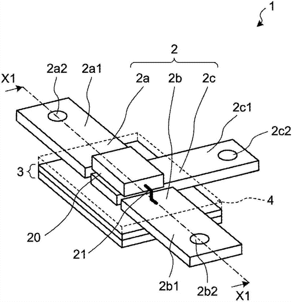
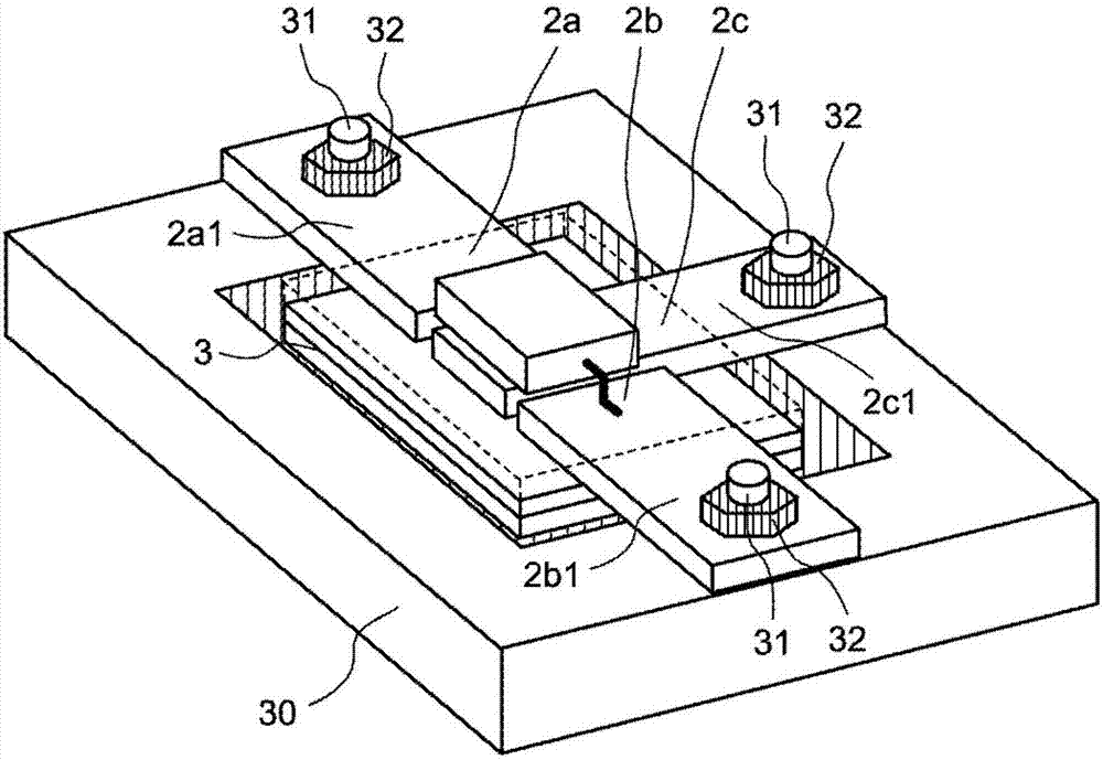
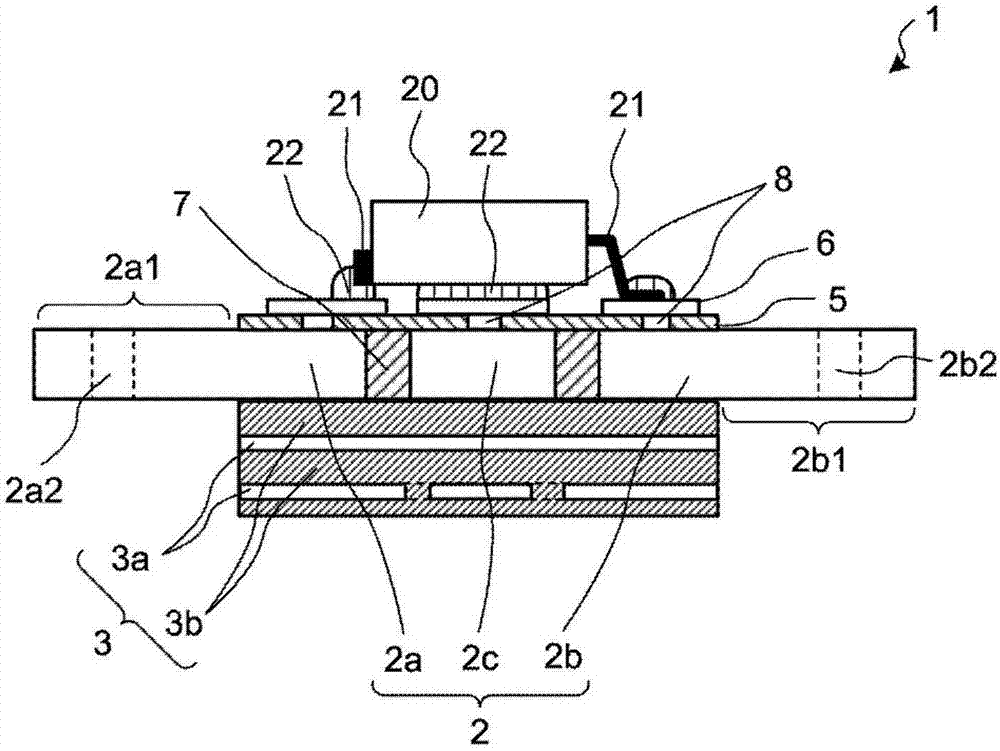
[0020] figure 1 is a perspective view showing the structure of the printed wiring board 1 according to the first embodiment. The printed wiring board 1 according to the present embodiment is effectively used for a printed wiring board used in an electronic controller mounted on a vehicle (for example, an electronic controller for controlling large power / high load when controlling a motor or the like). On the other hand, the use of the printed wiring board 1 according to the present embodiment is not limited to electronic controllers.
[0021] Such as figure 1 As shown, the printed wiring board 1 according to the first embodiment includes a metal plate 2 and a wiring member 3 arranged on or over the back surface of the metal plate 2 . Metal plate 2 includes current path parts 2 a and 2 b , which are main current paths that supply large current to electronic part 20 , and heat dissipation part 2 c that dissipates heat generated by electronic part 20 .
[0022] Here, in the pr...
no. 2 example
[0060] Figure 6 is a top view showing a printed wiring board 1C according to the second embodiment.
[0061] The difference between the printed wiring board 1C according to the second embodiment and the printed wiring board 1 according to the first embodiment is the circuit structure. A conductive plate 9 is added on or above the back of the wiring member 3 to realize different circuit structures.
[0062] Such as Figure 6 As shown, a printed wiring board 1C according to the second embodiment includes a metal plate 2 , a wiring member 3 and a conductive plate 9 . The metal plate 2 includes: current path parts 2a and 2b as main current paths of the plurality of electronic parts 20a to 20d; and heat dissipation parts 2c and 2d that dissipate heat generated by the electronic parts 20a to 20d.
[0063] Furthermore, the current path parts 2a and 2b and the heat dissipation parts 2c and 2d are integrally formed with the wiring member 3 in the same layer. Therefore, like the pr...
PUM
| Property | Measurement | Unit |
|---|---|---|
| Thickness | aaaaa | aaaaa |
| Thickness | aaaaa | aaaaa |
Abstract
Description
Claims
Application Information
 - R&D Engineer
- R&D Manager
- IP Professional
- Industry Leading Data Capabilities
- Powerful AI technology
- Patent DNA Extraction
Browse by: Latest US Patents, China's latest patents, Technical Efficacy Thesaurus, Application Domain, Technology Topic, Popular Technical Reports.
© 2024 PatSnap. All rights reserved.Legal|Privacy policy|Modern Slavery Act Transparency Statement|Sitemap|About US| Contact US: help@patsnap.com


