
Receiver tracking apparatus and method for realizing receiver tracking

A technology of a tracking device and a receiver, applied in the field of receiver tracking, can solve the problems of poor dynamic performance, inability to adjust the coherent integration duration, and deterioration of the tracking accuracy of a phase-locked loop.

Inactive Publication Date: 2017-10-31
DATANG SEMICON DESIGN
View PDF3 Cites 7 Cited by
  • Summary
  • Abstract
  • Description
  • Claims
  • Application Information

AI Technical Summary

Problems solved by technology

[0005] Although the above method hopes to improve the performance of the carrier tracking circuit by combining the advantages of the frequency-locked loop and the phase-locked loop, the dynamic performance and the tracking accuracy cannot be taken into account
When the receiver is in a high dynamic environment, the tracking loop uses a frequency-locked loop, which can only take into account the dynamic adaptability of the tracking, and its tracking performance will be very poor
When the receiver is in a low-to-medium dynamic environment, the tracking loop chooses a phase-locked loop, which can only take into account the high-precision performance of tracking, and its dynamic performance will be poor
When the signal received by the receiver is very weak, the integration part will choose a longer integration time to improve the signal-to-noise ratio of the signal, and a longer integration time will greatly damage the dynamic performance of the frequency-locked loop
When the signal received by the receiver is very strong, if the integration time is too long at this time, the tracking accuracy of the phase-locked loop will be seriously deteriorated
Therefore, the methods in the related art cannot adjust the duration of the coherent integration in real time according to the environment of the loop tracking, and take into account the tracking accuracy while ensuring the dynamic performance of the tracking loop

Method used


Image

  • Receiver tracking apparatus and method for realizing receiver tracking
  • Receiver tracking apparatus and method for realizing receiver tracking
  • Receiver tracking apparatus and method for realizing receiver tracking

Examples


Embodiment Construction

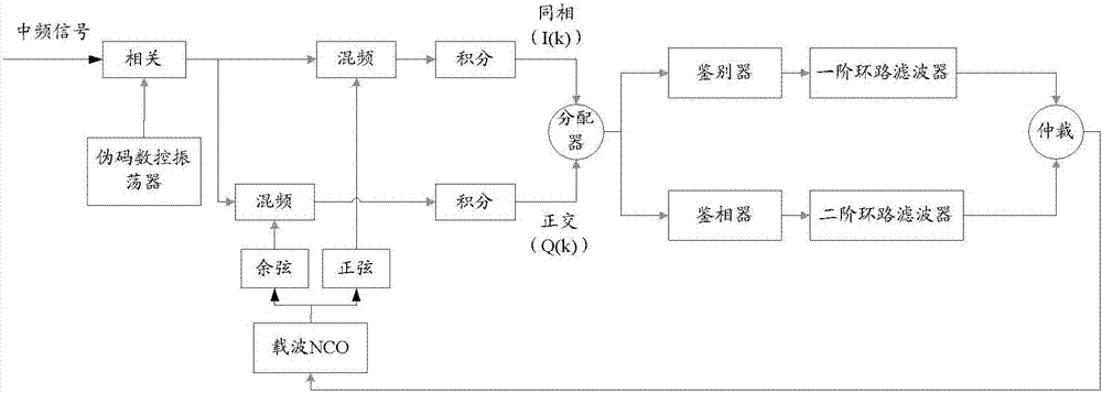
[0096] In order to make the purpose, technical solution and advantages of the present invention more clear, the embodiments of the present invention will be described in detail below in conjunction with the accompanying drawings. It should be noted that, in the case of no conflict, the embodiments in the present application and the features in the embodiments can be combined arbitrarily with each other.

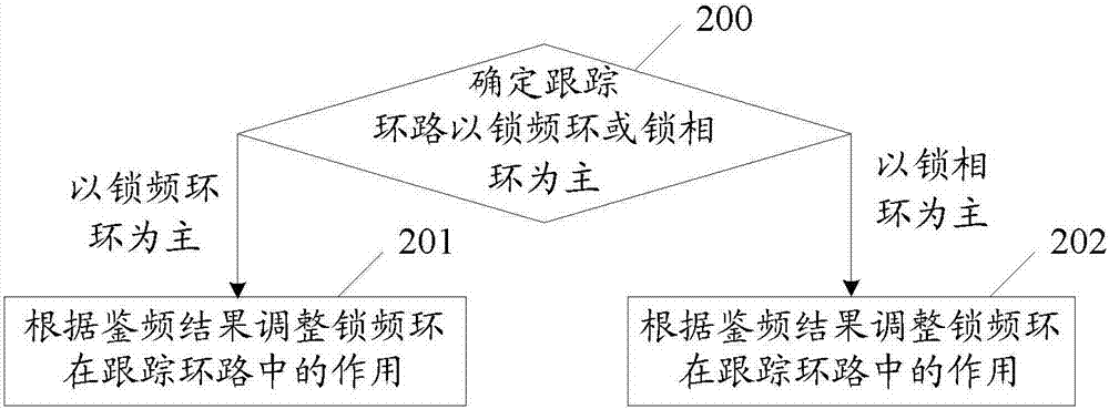
[0097] figure 2 A flow chart of a method for implementing receiver tracking in an embodiment of the present invention, such as figure 2 shown, including:

[0098] Step 200, determining that the tracking loop is mainly frequency-locked loop (FLL) or phase-locked loop (PLL);

[0099] When it is determined that the tracking loop is dominated by a frequency-locked loop, perform step 201; when it is determined that the tracking loop is mainly based on a phase-locked loop, perform step 202;

[0100] It should be noted that the integration result here is the result obtained by ...


PUM


Abstract

The embodiment of the invention discloses a receiver tracking apparatus and a method for realizing receiver tracking. The method comprises: a tracking loop is determined to relying on a frequency locked loop (FLL) or a phase locked loop (PLL); for the tracking loop relying on the frequency locked loop, according to a frequency discrimination result, the effect of the frequency locked loop in the tracking loop is adjusted; and for the tracking loop relying on the phase locked loop, the effect of the phase locked loop in the tracking loop is adjusted based on a frequency discrimination result. According to the method disclosed by the invention, the tracking loop relying on the frequency locked loop or the phase locked loop is adjusted based on the frequency discrimination result, thereby realizing the dynamic performance and tracking precision of the tracking loop simultaneously; and on the basis of a carrier to noise ration, the time length of the coherent integration is determined, so that the time length of the coherent integration is adjusted timely.

Description

technical field [0001] The invention relates to receiver tracking technology, in particular to a receiver tracking device and a method for realizing receiver tracking. Background technique [0002] Global Navigation Satellite System (GNSS, Global Navigation Satellite System) is playing an increasingly irreplaceable role in people's daily life, especially in the fields of navigation, exploration, monitoring, measurement, communication timing, etc. . With the rapid development of civilian applications in recent years, the global satellite navigation system has gradually deepened in daily life. From mobile phones, personal computers, automobiles, civil aircraft to missiles and fighters, satellite navigation technology is inseparable. All major countries in the world are striving to develop satellite navigation technology. Currently, there are multiple satellite navigation systems. Countries compete independently to develop satellite navigation technology and mutually compatibl...

Claims


Application Information

Patent Timeline
IPC IPC(8): G01S19/29
CPCG01S19/29
Inventor 宋挥师徐雄伟刘晓燕孙涛刘航赵海龙
Owner DATANG SEMICON DESIGN
Learn More