
Method and control device for operating a gas engine

A gas engine, mode control technology, applied in the direction of engine control, combustion engine, internal combustion piston engine, etc., can solve the problems of low knock tendency, poor main combustion chamber, etc., achieve high engine efficiency, low knock tendency, reduce The effect of exhaust gas recirculation

Inactive Publication Date: 2017-10-31
MAN ENERGY SOLUTIONS SA
View PDF5 Cites 2 Cited by
  • Summary
  • Abstract
  • Description
  • Claims
  • Application Information

AI Technical Summary

Problems solved by technology

Because the main combustion chamber is very lean, only small amounts of NOx are produced and there is only a low tendency to knock, making high performance density and high efficiency possible

Method used


Image

  • Method and control device for operating a gas engine
  • Method and control device for operating a gas engine

Examples


Embodiment Construction

[0019] The invention relates to a method for operating a gas engine and to a device for carrying out said method.

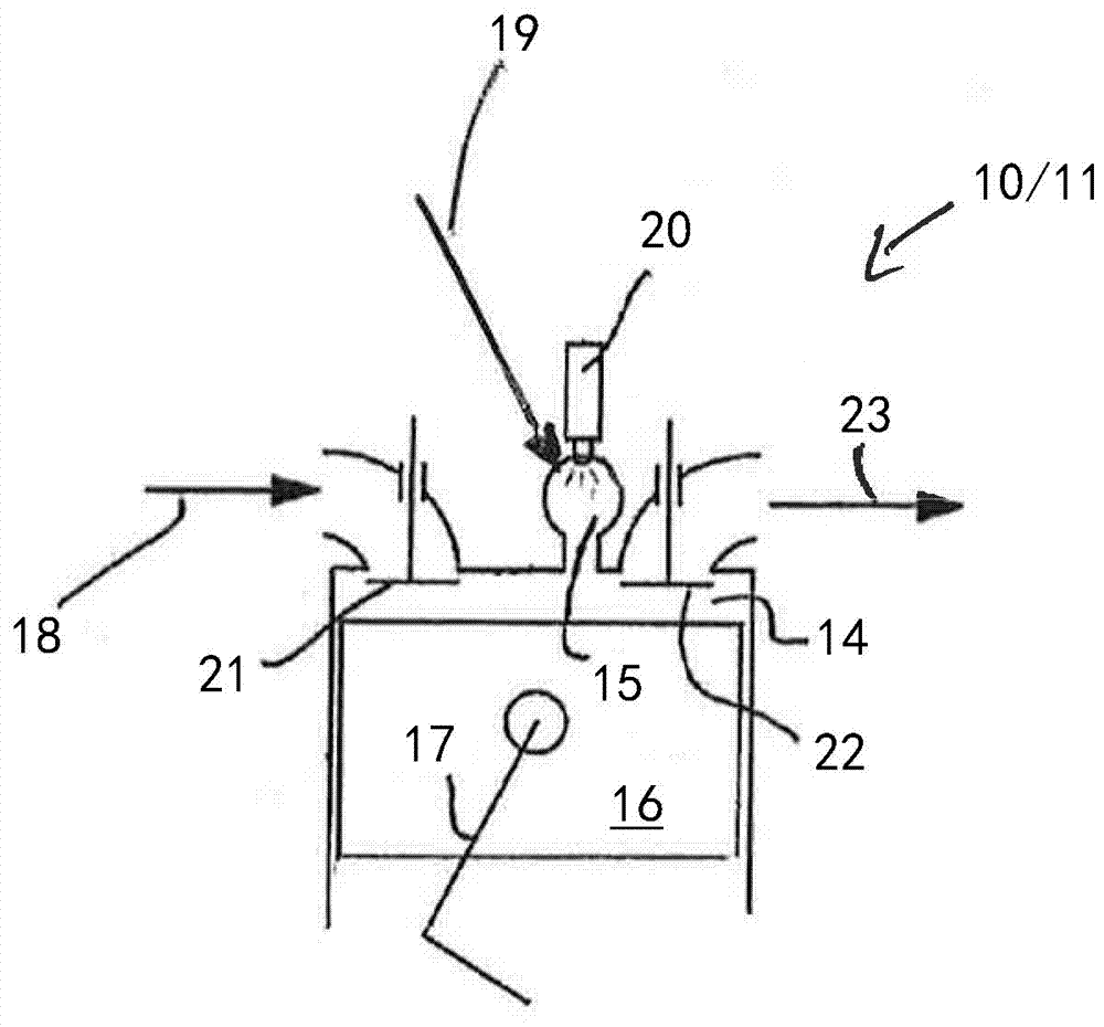
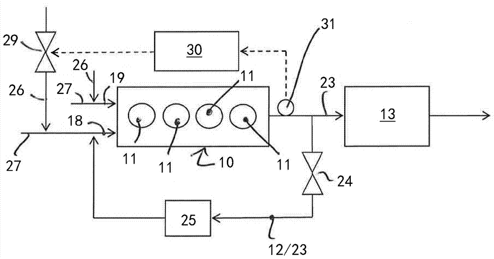
[0020] figure 1 A highly schematic block diagram of a gas engine 10 with a plurality of cylinders 11 , with an exhaust gas recirculation device 12 and an exhaust gas catalytic converter 13 is shown. figure 2 A detail of the gas engine 10 is shown in the region of the cylinders 11 of said gas engine 10 .

[0021] Each cylinder 11 of the gas engine 10 includes a main combustion chamber 14 and a pre-combustion chamber 15 coupled to the main combustion chamber 14 . In the main combustion chamber 14 , the pistons 16 of the respective cylinders 11 move up and down, wherein the pistons 16 are coupled to a not shown crankshaft via connecting rods 17 .

[0022] The gas / air mixture 18 combusted in the main combustion chamber 14 of the respective cylinder 11 may be fed to the main combustion chamber 14 of the cylinder 11 of the gas engine 10 . A further gas / air mixture ...


PUM


Abstract

A method for operating a gas engine (10) with an exhaust gas catalytic converter (13) and with an exhaust gas recirculation (12), wherein the gas engine (10) comprises cylinders (11), which comprise a main combustion chamber (14) and a precombustion chamber (15), wherein the exhaust gas (23) leaving the cylinders (11) is conductible via the exhaust gas catalytic converter (13), and wherein a part of the exhaust gas (23) leaving the cylinders, is conductible via the exhaust gas recirculation (12) in the direction of the cylinders (11). In a first operating strategy, the gas engine (10) is operated in such a manner that exhaust gas (23) conducted via the exhaust gas recirculation (12) is conducted in the direction of the main combustion chambers (14) of the cylinders, so that the gas / air mixture (18) to be fed to the main combustion chambers contains exhaust gas; that exhaust gas (23) conducted via the exhaust gas recirculation is not conducted in the direction of the precombustion chambers (15) of the cylinders, so that the gas / air mixture (19) to be fed to the precombustion chamber does not contain any exhaust gas; that the gas proportion of the gas / air mixture (18) to be fed to the main combustion chambers (14) of the cylinders (11) is controlled in such a manner that the combustion in the cylinders takes place at a stoichiometric combustion air ratio or a lambda value of 1.

Description

technical field [0001] The invention relates to a method for operating a gas engine and to a control device for carrying out said method. Background technique [0002] Gas engines with an exhaust gas catalytic converter and an exhaust gas recirculation device are known from practice, wherein the exhaust gas generated in the cylinders of the gas engine during the combustion of the gas / air mixture can be guided via the exhaust gas catalytic converter and where the exit A part of the exhaust gases of the cylinders may be recirculated in the direction of the cylinders via the exhaust gas recirculation device or may be mixed with the gas / air mixture to be fed to the cylinders. [0003] Furthermore, gas engines according to the lean combustion method (super-stoichiometric ratio) are known, the cylinders of which comprise either only the main combustion chamber or pre-combustion chambers in addition to the main combustion chamber, where in the cylinder In the case of a gas engine ...

Claims


Application Information

Patent Timeline
Patent Type & Authority Applications(China)
IPC IPC(8): F02D21/08F02D19/02F02B43/00F02B19/00F02M26/17
CPCF02M26/00F02B19/00F02D19/02F02M26/17F02D21/08F02B43/00F02D19/023F02D2200/06F02B19/1028Y02T10/12Y02T10/30F02M26/13F02D41/0047F02D41/006F02D41/0065
Inventor C.孔克尔
Owner MAN ENERGY SOLUTIONS SA
Learn More