
Continuously-adjustable tourniquet device

A cuff and adjustable technology, applied in the direction of tourniquet, etc., can solve the problems of difficult control of pressure, low work efficiency, high work intensity, etc., and achieve the effect of reducing work intensity, high work efficiency and improving work efficiency

Active Publication Date: 2017-10-24
TIANJIN HAIMAI MEDICAL TECH
View PDF11 Cites 4 Cited by
  • Summary
  • Abstract
  • Description
  • Claims
  • Application Information

AI Technical Summary

Problems solved by technology

Due to the difficulty in controlling the pressure during the use of the existing cuff, and in special patient populations such as patients with edema or patients who need to puncture the lower limbs, it often causes damage to the patient and leads to skin damage
At the same time, the cuff needs to be manually bundled and disassembled every time it is used, which makes the medical staff work intensively and have low work efficiency.

Method used


Image

  • Continuously-adjustable tourniquet device
  • Continuously-adjustable tourniquet device
  • Continuously-adjustable tourniquet device

Examples


Embodiment Construction

[0016] It should be noted that, in the case of no conflict, the embodiments of the present invention and the features in the embodiments can be combined with each other.

[0017] In describing the present invention, it should be understood that the terms "center", "longitudinal", "transverse", "upper", "lower", "front", "rear", "left", "right", " The orientations or positional relationships indicated by "vertical", "horizontal", "top", "bottom", "inner" and "outer" are based on the orientations or positional relationships shown in the drawings, and are only for the convenience of describing the present invention and Simplified descriptions, rather than indicating or implying that the device or element referred to must have a particular orientation, be constructed and operate in a particular orientation, and thus should not be construed as limiting the invention. In addition, the terms "first", "second", etc. are used for descriptive purposes only, and should not be understood ...


PUM


Abstract

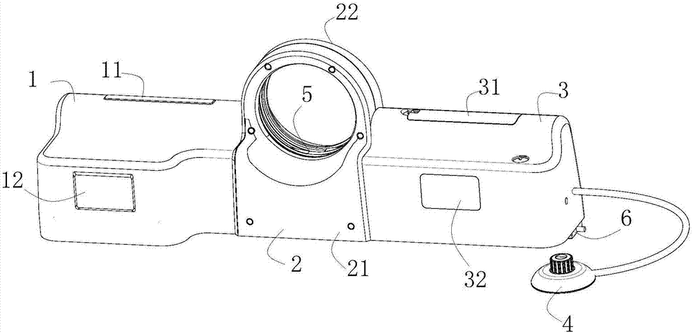
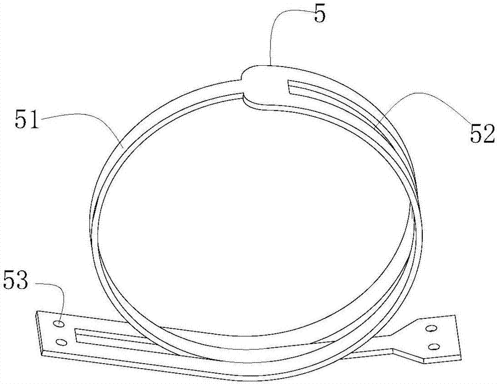
The invention relates to a continuously-adjustable tourniquet device. The tourniquet device comprises a tourniquet shell. The tourniquet shell comprises a left shell body, a middle shell body, a right shell body and a bottom plate. A tourniquet is installed in the middle shell body, a motor is installed at the left front end of the bottom plate, a rotating belt wheel is installed at the motor output shaft end of the motor, a bottom sliding rail positioning plate is installed in the middle of the bottom plate, a first sliding rail is installed on the sliding rail positioning plate, a first sliding base is installed in the first sliding rail, the two ends of the first sliding base are fixedly connected with a working belt, a left rear supporting plate and a right rear supporting plate are installed at the left rear end and the right rear end of the bottom plate respectively, a left guide wheel is installed at the left upper end of the left rear supporting plate, a second sliding rail is installed on the left rear supporting plate, a second sliding base is installed in the second sliding rail, the upper end of the second sliding base is fixedly connected with the left end of the tourniquet, a first right guide wheel and a second right guide wheel are installed on the right of the right rear supporting plate, a third sliding rail is installed on the left side of the first right guide wheel, a third sliding block is installed in the third sliding rail, and the upper end of the third sliding block is fixedly connected with the right end of the tourniquet.

Description

technical field [0001] The invention relates to a continuously adjustable cuff device. Background technique [0002] Before venipuncture, medical personnel usually tie an elastic cuff on the upper part of the patient's puncture to slow down the return of venous blood, so that the local blood vessels can be filled to facilitate successful puncture, and at the same time, it is convenient to draw enough venous blood. The current tourniquet is generally cut from an ordinary elastic silicone tube. Because the diameter of the silicone tube is small, the force-bearing area at the binding site is small, and the pressure on the body tissue is relatively large. Feel pain of varying degrees. Because the pressure is difficult to control during the use of the existing cuff, and in special patient groups such as edema patients or patients who need to puncture the lower limbs, it often causes damage to the patient and leads to skin damage. At the same time, the cuff needs to be manually ...

Claims


Application Information

Patent Timeline
Patent Type & Authority Applications(China)
IPC IPC(8): A61B17/132
CPCA61B17/1322Y02A50/30
Inventor 杨弘崔程明
Owner TIANJIN HAIMAI MEDICAL TECH
Learn More