Signal collision separation method and device

A separation method and signal technology, applied in the field of aviation surveillance, can solve problems such as increased computational complexity, and achieve the effects of reducing complexity, reducing matrix dimensions, and effectively separating

Active Publication Date: 2020-02-18
天宇航空数据科技(合肥)有限责任公司
View PDF1 Cites 0 Cited by
  • Summary
  • Abstract
  • Description
  • Claims
  • Application Information

AI Technical Summary

Problems solved by technology

[0003] The existing projection algorithm is based on knowing that only two signals collide, and converts the single-channel situation into a multi-channel situation to separate the collision signals, so it can only separate the two signal collision situations; the existing blind signal separation Algorithms (such as constant coefficient invariant separation algorithm and Manchester decoding algorithm) use the zeroing characteristic of the source signal as a constraint, and separate the colliding aliasing signals based on the solution matrix equation. As the number of signal collisions increases, The computational complexity of the algorithm increases exponentially

Method used


Image

  • Signal collision separation method and device
  • Signal collision separation method and device
  • Signal collision separation method and device

Examples


Embodiment Construction

[0023] In order to make the purposes, technical solutions and advantages of the embodiments of the present invention clearer, the technical solutions in the embodiments of the present invention will be clearly and completely described below with reference to the accompanying drawings in the embodiments of the present invention. Obviously, the described embodiments These are some embodiments of the present invention, but not all embodiments. Based on the embodiments of the present invention, all other embodiments obtained by those of ordinary skill in the art without creative efforts shall fall within the protection scope of the present invention.

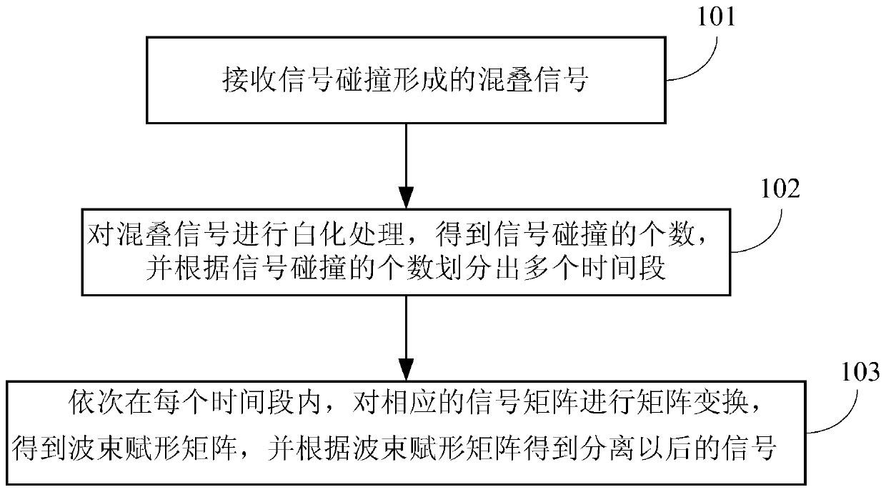
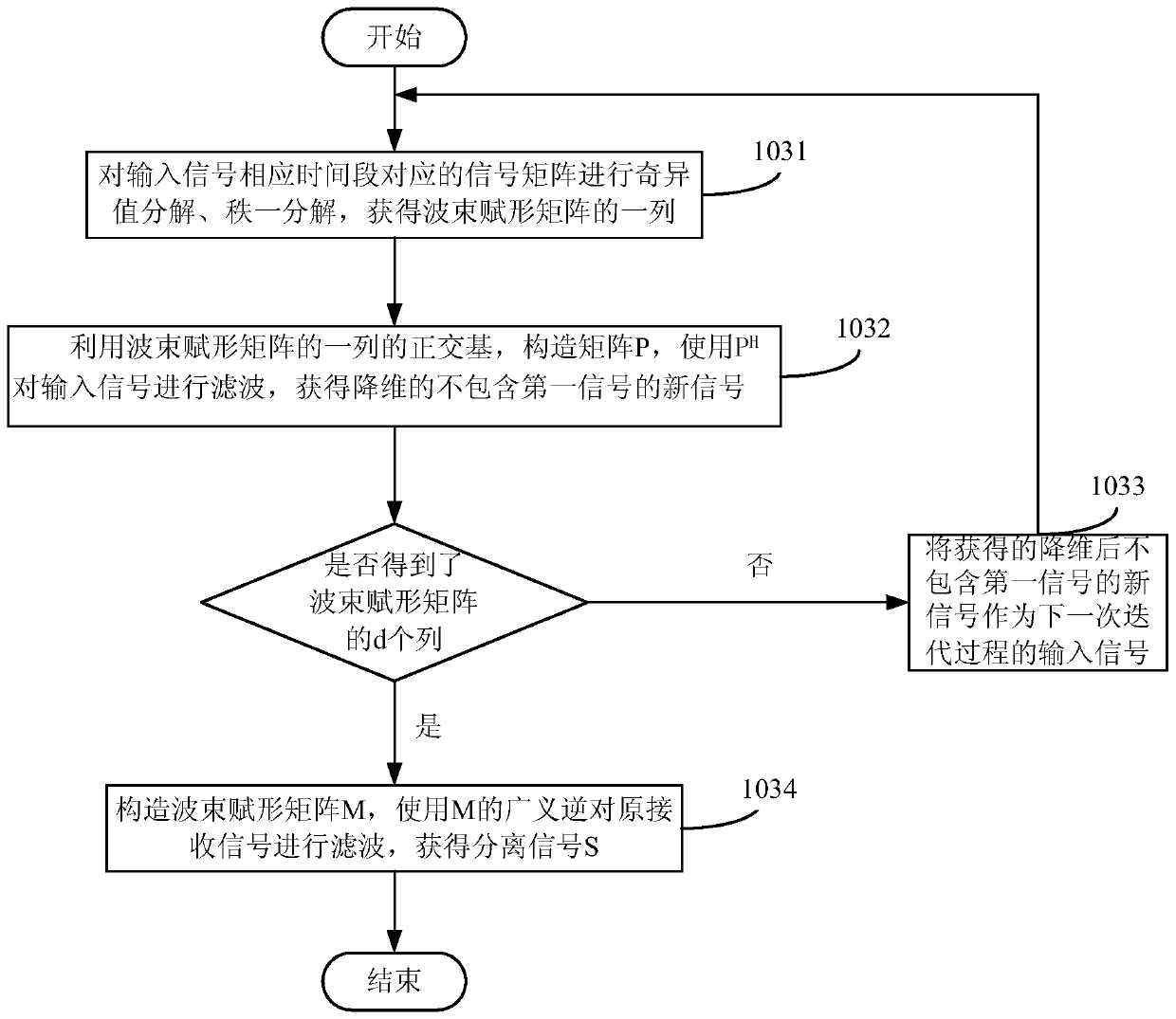
[0024] figure 1 It is a flow chart of Embodiment 1 of the signal collision separation method of the present invention, as figure 1 As shown, the method of this embodiment may include:

[0025] Step 101, receiving an aliased signal formed by signal collision;

[0026] The present invention can be based on various forms of signals ...


PUM


Abstract

The invention provides a signal collision separation method and apparatus. The signal collision separation method provided by the invention comprises the following steps: receiving an aliasing signal formed by signal collision; performing whitening processing on the aliasing signal to obtain the number of signal collision, and dividing a plurality of time periods according to the number of signal collision; and performing matrix transformation on a corresponding signal matrix within each time period to obtain a beam forming matrix, and obtaining separated signals according to the beam forming matrix. By adoption of the signal collision separation method and apparatus, the complexity of separation algorithm of multiple signal collision is reduced.

Description

technical field [0001] The invention relates to aerial surveillance technology, in particular to a signal collision separation method and device. Background technique [0002] Satellite-based broadcast automatic dependent surveillance (Automatic Dependent Surveillance–Broadcast, referred to as: ADS-B) technology is to carry the ADS-B receiver on the satellite platform as a part of the satellite load, and use the large-scale coverage of the satellite to realize the monitoring of aviation nodes. A new type of aerial surveillance technology for large-scale surveillance. Due to the relatively wide coverage of satellite nodes, there are often multiple aircrafts operating at the same time within its coverage. When each aircraft broadcasts its own ADS-B signal, the ADS-B receiver will receive an aliased signal where many ADS-B signals collide together. Proper separation of the aliased signals is required for the ADS-B receiver to obtain the ADS-B information for each aircraft. ...

Claims


Application Information

Patent Timeline
Patent Type & Authority Patents(China)
IPC IPC(8): H04L25/03H04B7/08
CPCH04B7/086H04L25/0391
Inventor 张涛丁洋刘雪飞
Owner 天宇航空数据科技(合肥)有限责任公司
Why Eureka
Try Eureka