
Photomask and exposure method based on the photomask

An exposure method and photomask technology, which are applied in the field of photomask and exposure based on the photomask, can solve the problems of small pattern thickness, unfavorable large-size pattern manufacturing, and patterns that do not meet production requirements, so as to avoid multiple exposures and effectively Facilitate the manufacture of large-scale patterns

Active Publication Date: 2021-01-26
WUHAN CHINA STAR OPTOELECTRONICS TECH CO LTD
View PDF8 Cites 0 Cited by
  • Summary
  • Abstract
  • Description
  • Claims
  • Application Information

AI Technical Summary

Problems solved by technology

This phenomenon of multiple exposures in the same pattern area can easily lead to the final pattern not meeting the production requirements, for example, the thickness of the pattern in this area is small, which is not conducive to the manufacture of large-scale patterns

Method used


Image

  • Photomask and exposure method based on the photomask
  • Photomask and exposure method based on the photomask
  • Photomask and exposure method based on the photomask

Examples


Embodiment Construction

[0016] The following will clearly and completely describe the technical solutions of each exemplary embodiment provided by the present invention with reference to the accompanying drawings in the embodiments of the present invention. In the case of no conflict, the following embodiments and technical features thereof can be combined with each other.

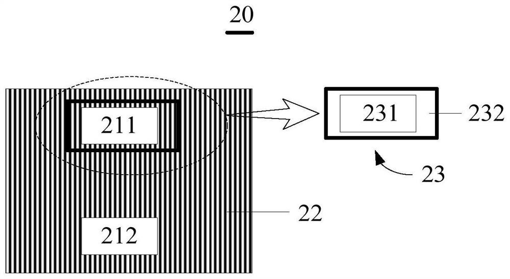
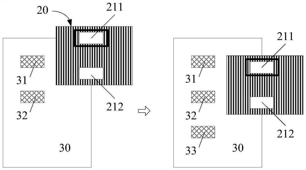
[0017] figure 2 is a schematic structural diagram of a photomask according to an embodiment of the present invention. Such as figure 2 As shown, the photomask 20 of this embodiment can be a plate structure, which includes two display opening areas and a shielding area 22 except for the two display opening areas, and the two display opening areas are respectively arranged up and down. The first display opening area 211 and the second display opening area 212 . In the photomask manufacturing process, the shielding area 22 is used to block light from passing through, and the display opening area allows light to pass through, so...


PUM


Abstract

The invention discloses a photomask and an exposure method based on the photomask. The photomask is provided with a display screen in its display opening area, and the display screen is used to control the light transmittance of the display opening area according to the received electric driving signal. Based on this, the present invention can avoid multiple exposures of the same pattern area in multiple photomask manufacturing processes, which is beneficial to the manufacture of large-scale patterns.

Description

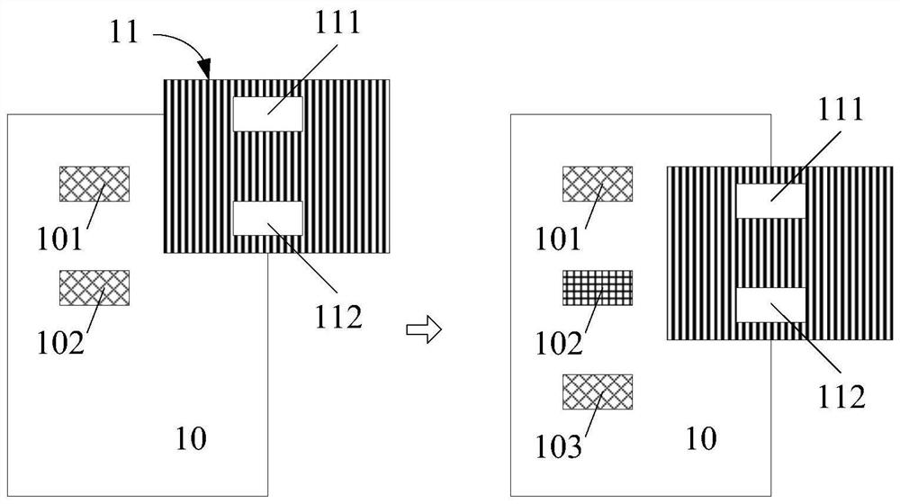
technical field [0001] The present invention relates to the field of display technology, in particular to the field of exposure technology, and in particular to a mask (Mask) and an exposure method based on the mask. Background technique [0002] Currently, in order to form a predetermined pattern on a large-area substrate, multiple photomask processes are required. by figure 1 The two photomask manufacturing processes shown are taken as an example. After the first photomask manufacturing process, patterns 101 and 102 corresponding to the first display opening area 111 and the second display opening area 112 of the photomask 11 are formed on the substrate 10. , and then move the mask 11. In order to meet the pattern design requirements, it is necessary to align the second display opening area 112 with the predetermined area 103 of the substrate 10. At this time, the first display opening area 111 of the mask 11 overlaps with the area where the pattern 102 is located, which...

Claims


Application Information

Patent Timeline
Patent Type & Authority Patents(China)
IPC IPC(8): G03F1/38
CPCG03F1/38
Inventor 王威
Owner WUHAN CHINA STAR OPTOELECTRONICS TECH CO LTD
Learn More