
Liquid crystal display panel and liquid crystal display device

A liquid crystal display panel and array substrate technology, which is applied in optics, instruments, electrical digital data processing, etc., and can solve the problems of small occlusion area and color shift of display devices.

Active Publication Date: 2017-10-20
XIAMEN TIANMA MICRO ELECTRONICS
View PDF6 Cites 4 Cited by
  • Summary
  • Abstract
  • Description
  • Claims
  • Application Information

AI Technical Summary

Problems solved by technology

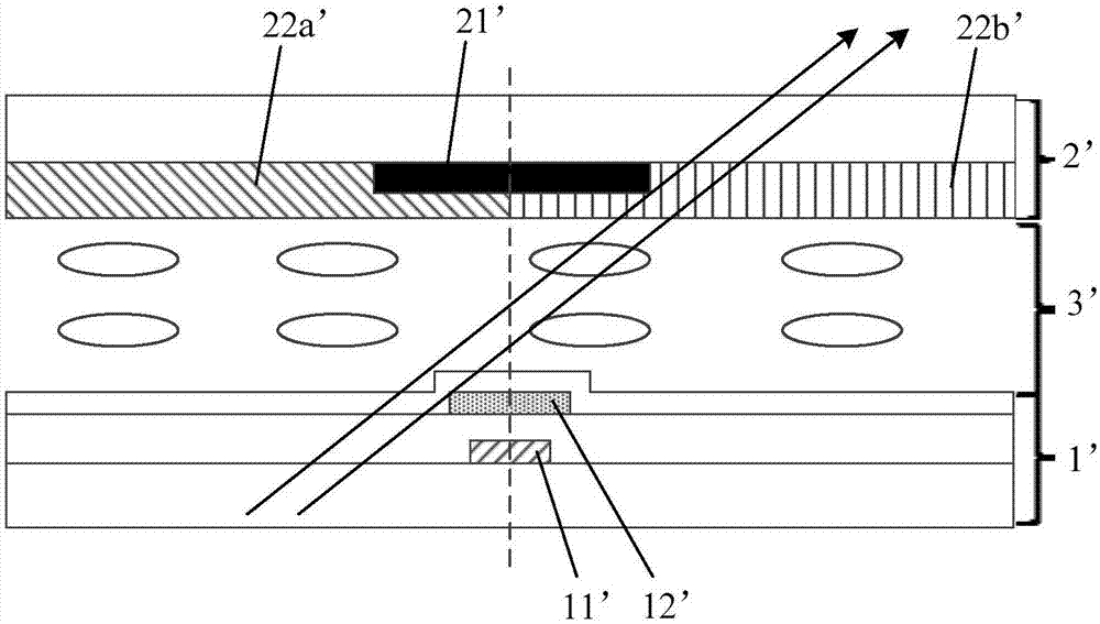
[0004] The inventors of the present application have found that in the prior art, there is also an electric field under the black matrix 21' during the display process, and the liquid crystal molecules under the black matrix 21' will also deflect, while the touch electrode leads 12', data lines 11' and the center line of the black matrix 21' parallel to the direction of the data line 11' coincide, so that the leads of the black matrix 21', the data line 11' and the touch electrode 12' are in an oblique direction (not perpendicular to the plane where the array substrate 1' is located) The shading area in the direction) is small, so that the oblique light can pass through the bottom of the black matrix 21' and exit the display device, that is, the light originally corresponding to the color resistance of one color is emitted from the color resistance of another color. Make the display device appear color shift phenomenon

Method used


Image

  • Liquid crystal display panel and liquid crystal display device
  • Liquid crystal display panel and liquid crystal display device
  • Liquid crystal display panel and liquid crystal display device

Examples


Embodiment Construction

[0040] In order to better understand the technical solutions of the present invention, the embodiments of the present invention will be described in detail below in conjunction with the accompanying drawings.

[0041] It should be clear that the described embodiments are only some of the embodiments of the present invention, not all of them. Based on the embodiments of the present invention, all other embodiments obtained by persons of ordinary skill in the art without creative efforts fall within the protection scope of the present invention.

[0042] It should be noted that, in the case of no conflict, the embodiments of the present invention and the features in the embodiments can be combined with each other. The present application will be described in detail below with reference to the accompanying drawings and embodiments.

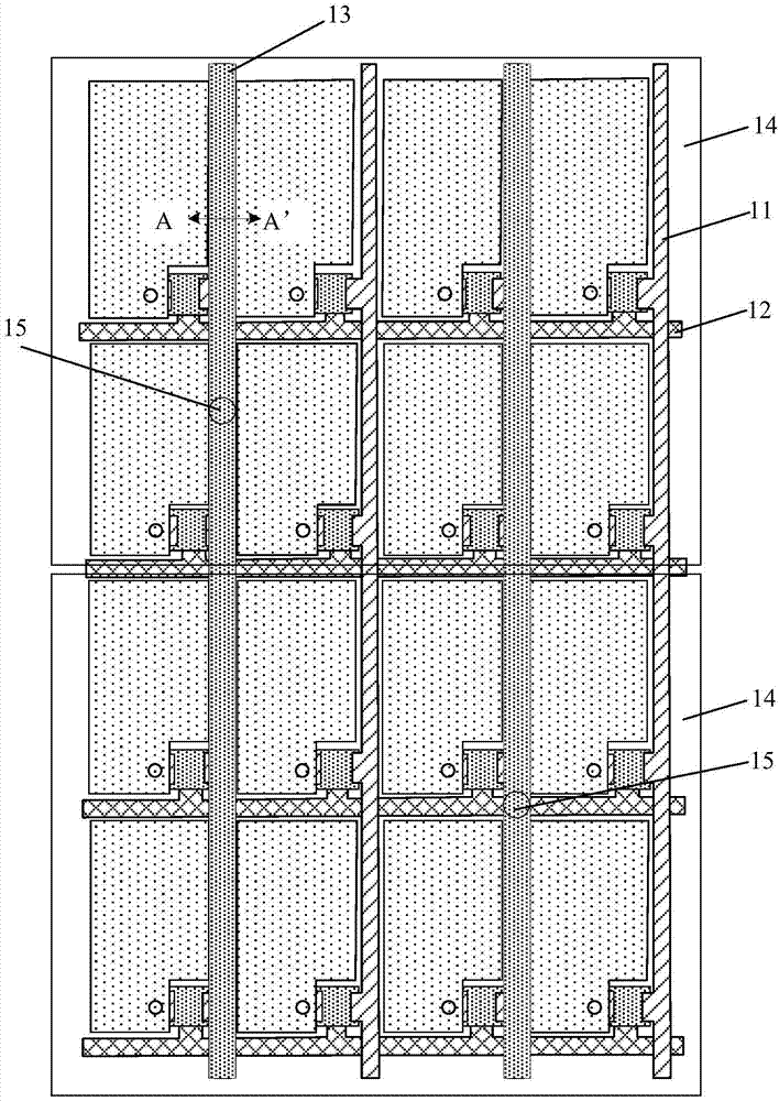
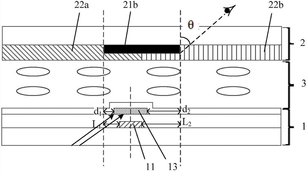
[0043] An embodiment of the present invention provides a liquid crystal display panel, such as figure 2 as shown, figure 2 It is a schematic cr...


PUM


Abstract

The embodiment of the invention provides a liquid crystal display panel and a liquid crystal display device, and relates to the technical field of display. In the liquid crystal display panel, a width L1 of a gap between edges of first sides of data lines of an array substrate and an orthographic projection of an edge of the a first side of a second black matrix corresponding to the data line on the array substrate is not equal to a width L2 of a gap between edges of second sides of the data lines and an orthographic projection of an edge of the a second side of the second black matrix on the array substrate; and / or a width d1 of a gap between edges of first sides of touch control electrode lead lines and an orthographic projection of the edge of the first side of the second black matrix corresponding to the touch control electrode lead lines on the array substrate is not equal to a width d2 of a gap between edges of second sides of the touch control electrode lead lines and an orthographic projection of the edge of the second side of the second black matrix on the array substrate. Accordingly, the technical scheme can solve the technical problem that colour cast of the liquid crystal display panel is serious in the prior art.

Description

【Technical field】 [0001] The invention relates to the field of display technology, in particular to a liquid crystal display panel and a liquid crystal display device. 【Background technique】 [0002] With the rapid development of display technology, users have higher and higher demands on the performance of display devices, and display devices with touch functions have emerged as the times require. Currently, the touch electrodes are usually integrated into the display panel of the display device (Touch Embed Display, TED for short) so that the display device has a touch function. [0003] like figure 1 as shown, figure 1 It is a schematic cross-sectional view of a liquid crystal display panel in the prior art. The liquid crystal display panel with a touch function includes an array substrate 1' and a color filter substrate 2' disposed opposite to each other, and an array substrate 1' and a color filter substrate 2' between the The liquid crystal layer 3', and the array s...

Claims


Application Information

Patent Timeline
IPC IPC(8): G02F1/1362G02F1/1333G06F3/041
CPCG02F1/13338G02F1/136286G06F3/0412
Inventor 崔宇张振铖朴哲邱英彰
Owner XIAMEN TIANMA MICRO ELECTRONICS
Learn More