
Waveguide display structure capable of improving visual experience

A technology for displaying structure and visual experience, applied in the field of optical waveguide, can solve the problems of increasing design, processing difficulty, high difficulty of waveguide design and processing, fixed diopter, etc., to achieve the effect of improving visual experience

Inactive Publication Date: 2017-10-20
SHANGHAI RAYPAI PHOTONIC CRYSTAL LTD
View PDF5 Cites 8 Cited by
  • Summary
  • Abstract
  • Description
  • Claims
  • Application Information

AI Technical Summary

Problems solved by technology

Patent 2015100311565 once proposed a waveguide structure design with diopter, which can alleviate the above problems to a certain extent, but the design and processing of the waveguide itself is very difficult, and this waveguide with diopter increases its design and processing difficulty. ; and once this waveguide is processed, its diopter is fixed and cannot be changed, so there are still problems in adaptability to wearers with different vision conditions
[0005] With the promotion of waveguide smart wearable devices, the visual experience problems caused by this optical waveguide display structure, which has strict vision requirements for the wearer, will become more prominent and serious.

Method used


Image

  • Waveguide display structure capable of improving visual experience
  • Waveguide display structure capable of improving visual experience
  • Waveguide display structure capable of improving visual experience

Examples


Embodiment Construction

[0021] The present invention will be further described in detail below in conjunction with the accompanying drawings and embodiments. It should be understood that the embodiments described here are only used to explain the present invention, but not to limit the present invention. In addition, it should be noted that, for the convenience of description, the traditional waveguide structure listed in this embodiment does not limit the "traditional waveguide" in the present invention. In fact, any display waveguide whose outgoing beam is parallel light can be considered to be included in the present invention. within the definition of "conventional waveguide".

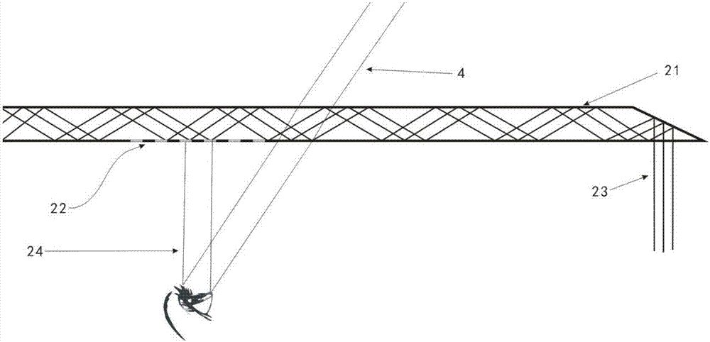
[0022] figure 1 It is an imaging display structure of a traditional waveguide. The parallel light 23 carrying image information travels in a way of total reflection inside the traditional waveguide 21. Destroyed, will fire from 22. In a traditional waveguide display structure, the light beam emitted from 22 is parallel...


PUM

PropertyMeasurementUnit
Diopteraaaaaaaaaa
Diopteraaaaaaaaaa

Abstract

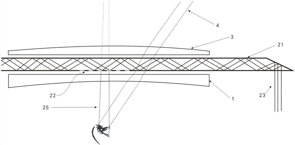
The invention discloses a waveguide display structure capable of improving visual experience. An imaging correcting lens with negative diopter is arranged at the near-to-eye end of a traditional waveguide, and a system correction lens with positive diopter is arranged at the other side of the traditional waveguide; the imaging correction lens and the system correction lens compensate each other; and the overall diopter of the waveguide display structure is zero. According to the waveguide display structure of the present invention, a display imaging structure is modified without changing the traditional waveguide, and therefore, the waveguide display structure of the invention has the advantages of simple structure and low processing cost. With the waveguide display structure adopted, people with impaired vision, people with corrected vision and people with normal vision, whose myopia degrees range from -120 degrees to 800 degrees, can see clear images in the waveguide, the display effect of the waveguide can be significantly improved, and the observation of the outside world by a wearer will not be affected. The waveguide display structure is of great significance for improving waveguide visual experience and popularizing waveguide display technology.

Description

technical field [0001] The invention belongs to the field of optical waveguide technology, and in particular relates to a waveguide display structure capable of improving visual experience. Background technique [0002] With the increasing application of augmented reality technology and head-up display technology in military affairs and daily life, people pay more and more attention to the visual experience of augmented reality and head-up display. Optical waveguide is an excellent carrier for reality augmentation because of its light weight, small size, compact structure, and thin thickness. [0003] However, the optical waveguide is limited by its display principle. The light beams entering the human eye from the waveguide are all parallel light. This display structure has high requirements on the human eye. Only wearers with no vision problems or very slight vision problems can see clearly For images, if the wearer’s eyesight is only 50 degrees of myopia, the light beam ...

Claims


Application Information

Patent Timeline
IPC IPC(8): G02B27/01
CPCG02B27/0101G02B27/0172
Inventor 孙川胡挺罗豪杜婷婷沈春明张圣军张庆
Owner SHANGHAI RAYPAI PHOTONIC CRYSTAL LTD
Learn More