Electric control board conveying device for new energy vehicle

A technology for new energy vehicles and conveying devices, applied in conveyors, transportation and packaging, etc., can solve the problems of management and control affecting conveying efficiency, inconvenient adjustment and control of feeding speed, and friction of electric control board, etc. Efficiency, the effect of convenient feeding speed

Inactive Publication Date: 2019-03-08
柳州英飞科技有限公司
View PDF0 Cites 3 Cited by
  • Summary
  • Abstract
  • Description
  • Claims
  • Application Information

AI Technical Summary

Problems solved by technology

[0003] With the rapid development of new energy vehicles, the demand for the output of new energy vehicles is increasing, and the requirements for the production equipment of new energy vehicles are also increasing, especially the electronic control boards with very high precision requirements, but the existing Because the electric control board conveying device for new energy vehicles cannot adjust the inclined structure during the feeding, the feeding speed is not easy to adjust and control, which greatly affects the control of the conveying efficiency, and the existing electric control board is extremely difficult during the conveying process. It is prone to deviation to both sides of the conveying direction, and the fixed limit structure will cause greater friction with the electric control board, which will seriously cause damage to the electric control board

Method used


Image

  • Electric control board conveying device for new energy vehicle
  • Electric control board conveying device for new energy vehicle
  • Electric control board conveying device for new energy vehicle

Examples


Embodiment Construction

[0024] The technical solutions in the embodiments of the present invention will be clearly and completely described below with reference to the accompanying drawings in the embodiments of the present invention. Obviously, the described embodiments are only a part of the embodiments of the present invention, but not all of the embodiments.

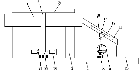
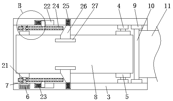
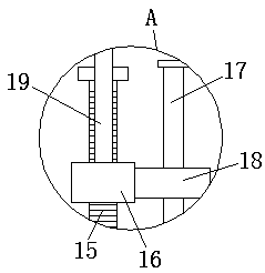
[0025] refer to Figure 1-5 , an electric control board conveying device for new energy vehicles, comprising a base plate 1, the top of the base plate 1 is fixedly connected with two symmetrical support legs 2, and the tops of the two support legs 2 are fixedly connected by a conveying U-shaped plate 3, and the conveying U-shaped plate 3 is fixedly connected. Mounting bearing seats 4 are fixedly connected to the inner surfaces of the front and back of the shaped plate 3, and the inner surfaces of the two mounting bearing seats 4 on one side close to each other are fixedly connected by the driven roller 5, and the inner surface of the front o...


PUM


Abstract

The invention discloses an electric control board conveying device for a new energy vehicle. The electric control board conveying device comprises a bottom plate, the top of the bottom plate is fixedly connected with two symmetrical support legs, the top ends of the two support legs are fixedly connected through a conveying U-shaped plate, a mounting bearing seat is fixedly connected to the innersurfaces of the front surface and the back surface of the conveying U-shaped plate, and the inner surfaces of the sides, getting close to each other, of the two mounting bearing seats are fixedly connected through a driven roller. According to the electric control board conveying device, a stepping motor is arranged to enable a threaded rod to rotate, a guiding sliding rod and a guiding bearing seat are arranged to limit a threaded block, the threaded rod rotates to move the threaded block in the up and down direction, the threaded block moves up and down to control angle changes caused when aforce applying rod extrudes a discharging plate to rotate, a worker can conveniently manage and control the discharging effect by reasonably controlling the inclined angle of the discharging plate, and the effect of facilitating the worker in managing and controlling the transportation efficiency is achieved.

Description

technical field [0001] The invention relates to the technical field of new energy vehicles, in particular to an electric control board conveying device for new energy vehicles. Background technique [0002] New energy vehicles refer to the use of unconventional vehicle fuels as the power source (or the use of conventional vehicle fuels and the use of new vehicle power units), and the integration of advanced technologies in vehicle power control and driving, resulting in advanced technical principles and features. New technology and new structure of the car. [0003] With the rapid development of new energy vehicles, the demand for the production of new energy vehicles is increasing, and the requirements for the production equipment of new energy vehicles are also increased, especially the electronic control boards with very high precision requirements, but the existing The new energy vehicle electric control board conveying device cannot adjust the inclined structure when c...

Claims


Application Information

Patent Timeline
IPC IPC(8): B65G25/04
CPCB65G25/04
Inventor 陈红姬
Owner 柳州英飞科技有限公司
Why Eureka
Try Eureka