Honeycombed-core structure
A honeycomb core and box technology, applied in building components, building structures, floor slabs, etc., can solve the problems of high scrap rate and difficulty in mold opening of honeycomb core, so as to simplify the structure, improve the prefabrication efficiency, and simplify the stripping process Effect
- Summary
- Abstract
- Description
- Claims
- Application Information
AI Technical Summary
Problems solved by technology
Method used
Image
Examples
Embodiment 1
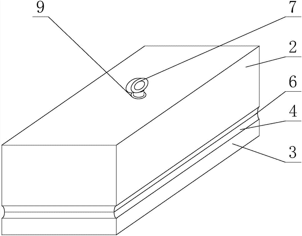
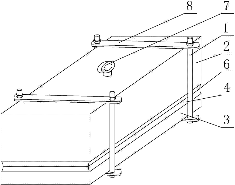
[0029] Such as Figure 1 to Figure 3 As shown, a honeycomb core structure includes a honeycomb core body, an annular ring groove 4 is also provided on the side of the honeycomb core body, and the honeycomb core body is spliced by an upper box body 2 and a lower box body 3 , and after the splicing of the upper box body 2 and the lower box body 3 is completed, the formed seam 6 is located at the bottom of the ring groove 4;
[0030] It also includes a filling layer filled in the joint 6, and the filling layer is formed of an adhesive material or is a sealing pad.
[0031] Specifically, the above annular groove 4 is a groove provided on the side of the honeycomb core body for embedding the steel wires constraining the position of the honeycomb core on the floor. When prefabricating the honeycomb core of the existing monolithic structure, since the corresponding mold needs to have a deformation part corresponding to the ring groove 4, there are complex procedures, complex mold ...
Embodiment 2
[0035] Such as Figure 1 to Figure 3 As shown, this embodiment is further limited on the basis of Embodiment 1: in order to ensure the connection strength between the upper box body 2 and the lower box body 3, and avoid the filling layer butt joint 6 of the honeycomb core structure during the transfer and hoisting process. The sealing performance fails, the upper box body 2 and the lower box body 3 are provided with steel mesh 5, and the steel mesh 5 of the upper box body 2 and the lower box body 3 are welded at the joint 6 position. As a person skilled in the art, the above steel mesh 5 is composed of reinforcement bars sandwiched in the bottom plate, top plate or side plate of the upper box body 2 or the lower box body 3, and is arranged in the above welding connection form, which can avoid 6 joints The joint surface of the honeycomb core structure is subjected to excessive tension during the transfer and hoisting of the honeycomb core structure.
[0036] As a structural sc...
Embodiment 3
[0043] This embodiment is further limited on the basis of any one of the technical solutions provided by any one of the above embodiments, such as Figure 1 to Figure 3 As shown, in order to avoid stress concentration at the position of the annular groove 4 when the honeycomb core structure is stressed, the cross section of the annular groove 4 is semi-elliptical or semicircular.
[0044] In order to improve the fire-resistant performance of the honeycomb core structure, refractory materials are laid on the outer surfaces of each surface of the honeycomb core body.
PUM
 Abstract
Description
Claims
Application Information
 - R&D
- Intellectual Property
- Life Sciences
- Materials
- Tech Scout
- Unparalleled Data Quality
- Higher Quality Content
- 60% Fewer Hallucinations
Browse by: Latest US Patents, China's latest patents, Technical Efficacy Thesaurus, Application Domain, Technology Topic, Popular Technical Reports.
© 2025 PatSnap. All rights reserved.Legal|Privacy policy|Modern Slavery Act Transparency Statement|Sitemap|About US| Contact US: help@patsnap.com


