Anti-vignetting method and device for spliced image, and terminal equipment
A technology of splicing images and images, which is applied in the field of image processing, can solve problems such as not being able to eliminate the vignetting effect of spliced images well, and achieve the effect of eliminating the vignetting effect and enhancing the imaging effect
- Summary
- Abstract
- Description
- Claims
- Application Information
AI Technical Summary
Problems solved by technology
Method used
Image
Examples
Embodiment 1
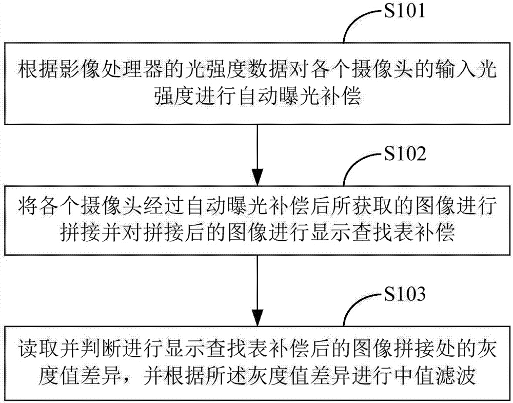
[0029] figure 1 A flow chart of a method for splicing images against vignetting provided by the first embodiment of the present invention is shown, and the details are as follows:
[0030] In step S101, automatic exposure compensation is performed on the input light intensity of each camera according to the exposure data of the image processor.
[0031] Due to the different positions of multiple cameras, different light incident directions such as forward light, backlight, and side light will be formed. Due to different light incident directions, the light incident amount of multiple cameras will be different, resulting in inconsistent brightness of the acquired images. Through the automatic exposure compensation of the input light intensity of each camera, multiple cameras can realize the linkage of exposure mechanism, that is, compare the exposure data of the image processors of multiple cameras, and then calculate the compensation value or suppression of the exposure data o...
Embodiment 2
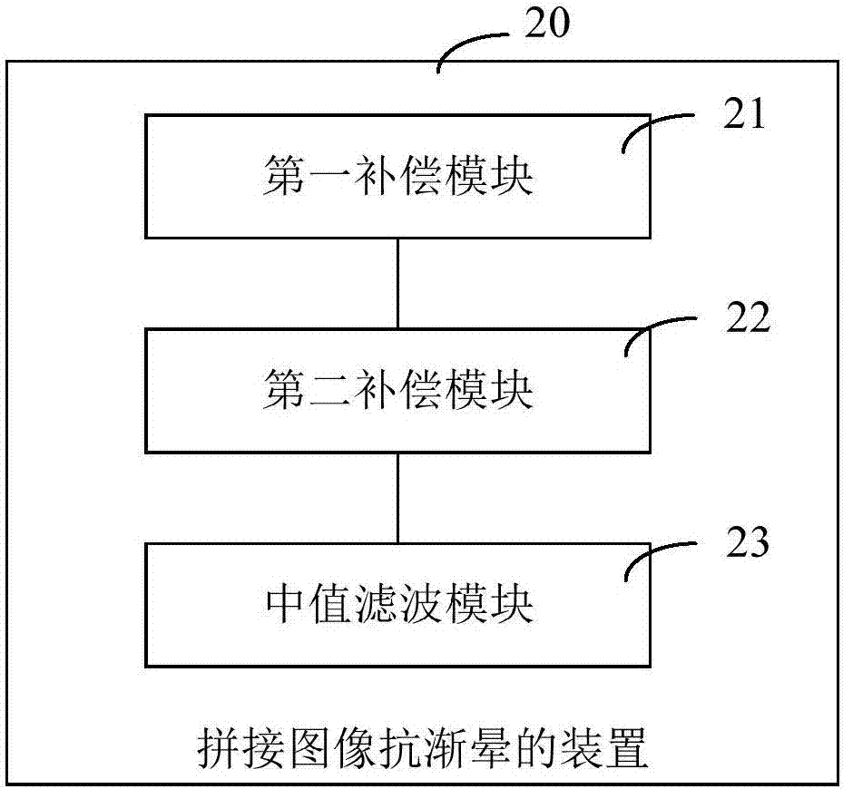
[0056] corresponds to figure 1 A method for splicing images to resist vignetting in the first embodiment shown, figure 2 A structural block diagram of the anti-vignetting device for splicing images provided by Embodiment 2 of the present invention is shown. For convenience of description, only parts related to the embodiment of the present invention are shown.
[0057] refer to figure 2 , the above-mentioned anti-vignetting device 20 for stitching images includes: a first compensation module 21 , a second compensation module 22 and a median filter module 23 .
[0058] The first compensation module 21 is used for performing automatic exposure compensation on the input light intensity of each camera according to the exposure data of the image processor.
[0059] The second compensation module 22 is used for stitching the images acquired by each camera after automatic exposure compensation and performing display lookup table compensation on the stitched images.
[0060] The ...
Embodiment 3
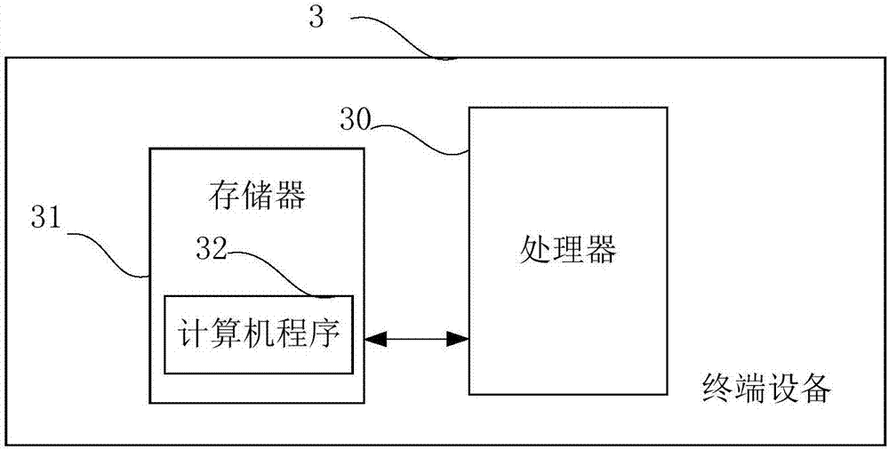
[0078] image 3 It is a schematic diagram of a terminal device provided by an embodiment of the present invention. Such as image 3 As shown, the terminal device 3 of this embodiment includes: a processor 30, a memory 31, and a computer program 32 stored in the memory 31 and operable on the processor 30, such as the program of the above-mentioned method for uninstalling an application program. When the processor 30 executes the computer program 32, the steps in the above-mentioned method embodiments for uninstalling application programs are implemented, for example figure 1 Steps S101 to S103 are shown. Alternatively, when the processor 30 executes the computer program 32, the functions of the modules / units in the above-mentioned device embodiments are realized, for example figure 2 Functions of modules 21 to 23 shown.
[0079] Exemplarily, the computer program 32 can be divided into one or more modules / units, and one or more modules / units are stored in the memory 31 and ...
PUM
 Abstract
Description
Claims
Application Information
 - R&D
- Intellectual Property
- Life Sciences
- Materials
- Tech Scout
- Unparalleled Data Quality
- Higher Quality Content
- 60% Fewer Hallucinations
Browse by: Latest US Patents, China's latest patents, Technical Efficacy Thesaurus, Application Domain, Technology Topic, Popular Technical Reports.
© 2025 PatSnap. All rights reserved.Legal|Privacy policy|Modern Slavery Act Transparency Statement|Sitemap|About US| Contact US: help@patsnap.com


