
Method and circuit for adjusting power supply efficiency

A power supply and circuit technology, applied in the field of maximum efficiency point calibration, can solve problems such as cumbersome debugging process, too subjective judgment basis, poor consistency of debugging results, etc., and achieve low hardware cost, optimized operating frequency, and improved work efficiency. Effect

Active Publication Date: 2019-08-09
ITECH ELECTRONICS NANJING
View PDF5 Cites 0 Cited by
  • Summary
  • Abstract
  • Description
  • Claims
  • Application Information

AI Technical Summary

Problems solved by technology

The existing debugging process is cumbersome, and the judgment basis is too subjective, and the consistency of the debugging results is not good

Method used


Image

  • Method and circuit for adjusting power supply efficiency
  • Method and circuit for adjusting power supply efficiency
  • Method and circuit for adjusting power supply efficiency

Examples


Embodiment Construction

[0037] The preferred embodiments of the present invention will be described below in conjunction with the accompanying drawings. It should be understood that the preferred embodiments described here are only used to illustrate and explain the present invention, and are not intended to limit the present invention.

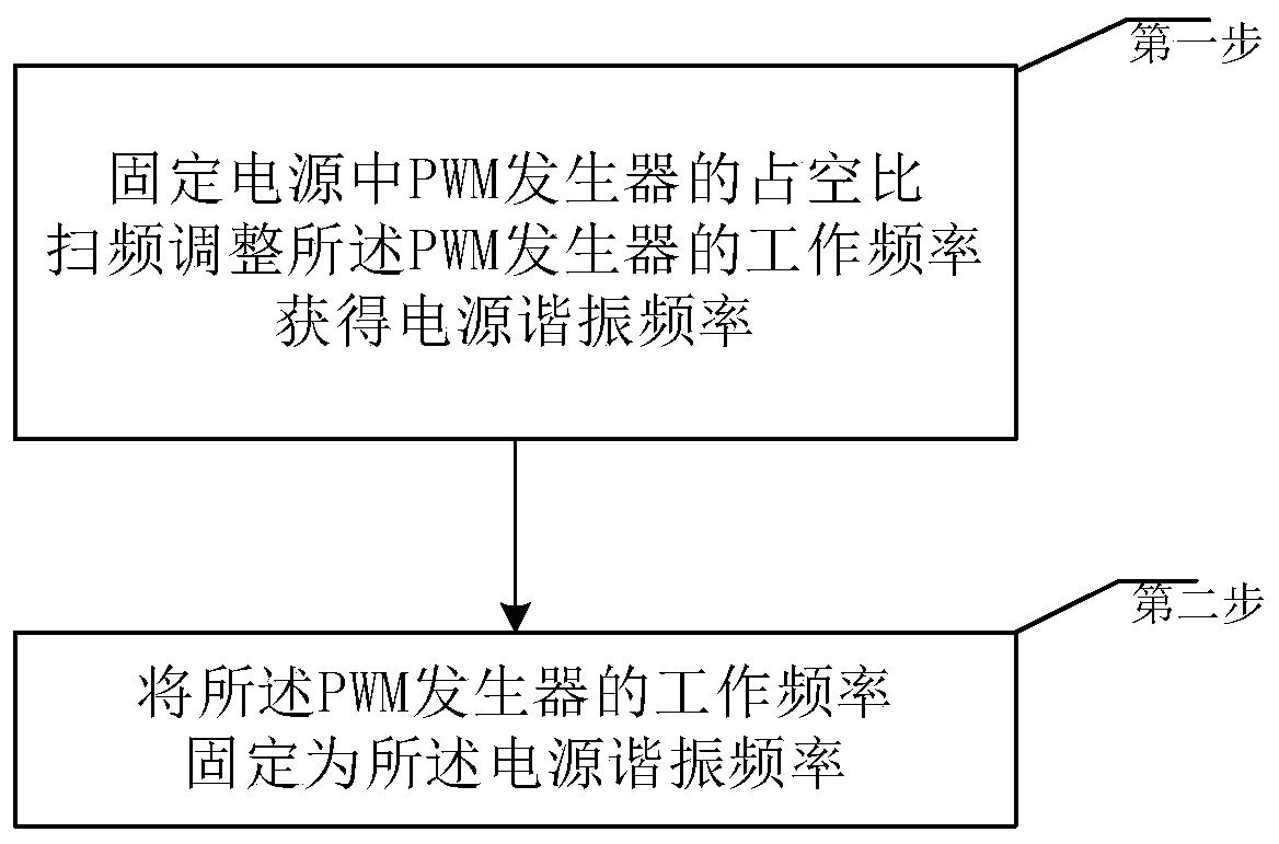
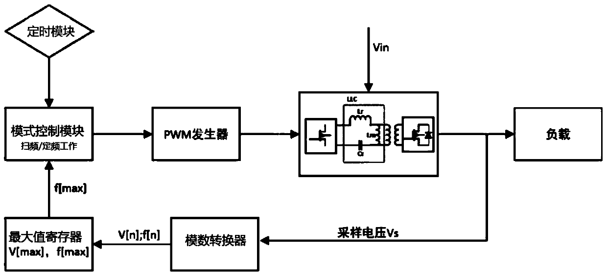
[0038] figure 1 It is a flow chart of the method for adjusting the operating frequency of the PWM generator in the power supply according to the present invention. apply it to figure 2 In the circuit for improving the working efficiency of the power supply shown, the circuit includes: an analog-to-digital converter, a maximum value register and a mode control module;

[0039] The input end of the analog-to-digital converter is connected to the output end of the power supply, the output end of the analog-to-digital converter is connected to the input end of the maximum value register, and the output end of the maximum value register is connected to the mode control...


PUM


Abstract

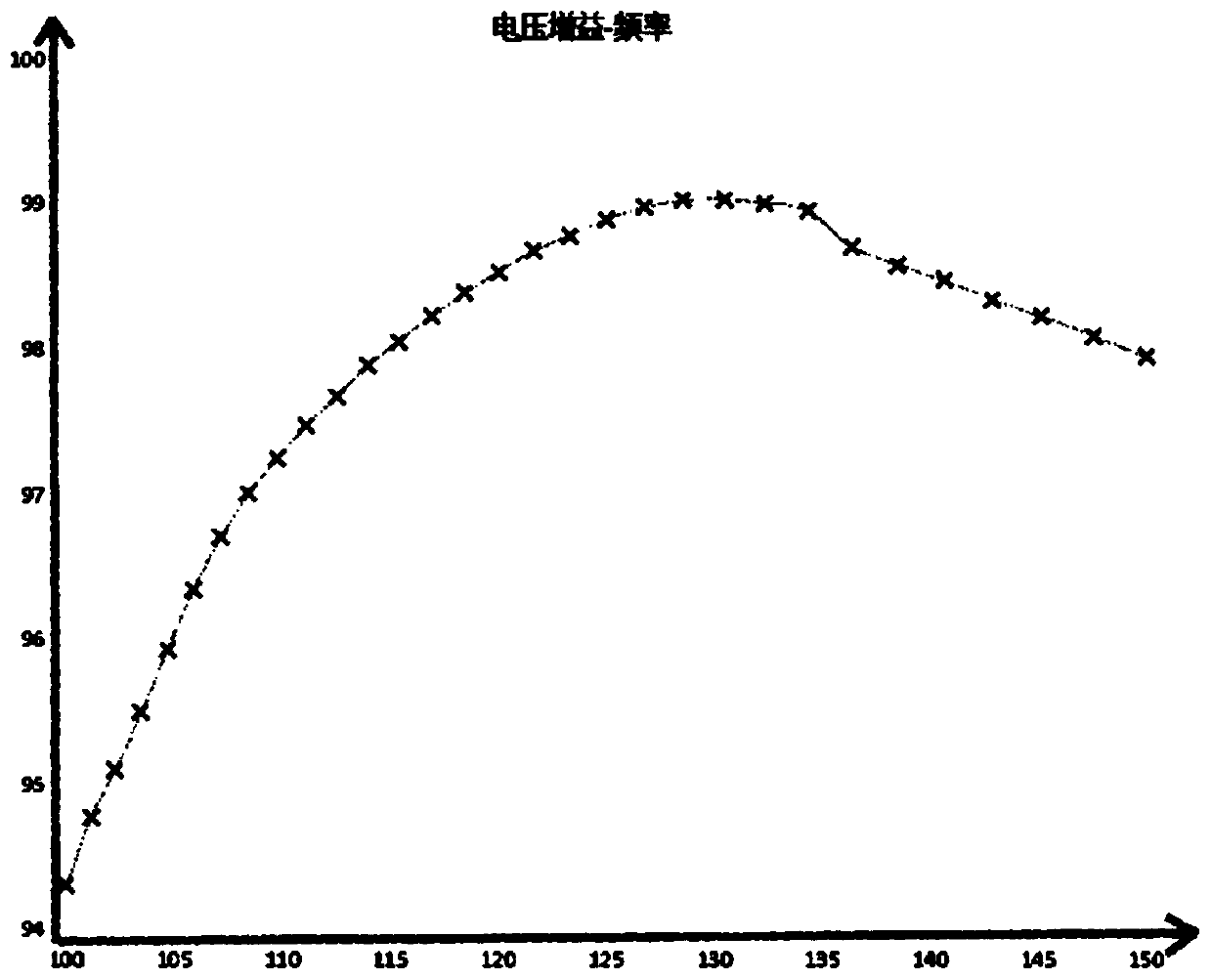
A method and circuit for adjusting power supply efficiency. The PWM generator in the power supply is controlled by a mode control module to perform frequency sweep first to obtain the power supply resonant frequency that maximizes the output voltage of the power supply. The frequency is stored in the maximum value register, and then works at a fixed frequency. mode, fix the operating frequency of the PWM generator to this frequency. Therefore, the circuit provided by the present invention can set the operating frequency of the power stage switching tube Q of the LLC resonant circuit in the power supply at the resonant frequency of the LLC circuit itself, thereby improving the working efficiency of the power supply. The present invention can realize the optimization of the working frequency of the power stage switching tube Q in the power supply only by using the existing analog-to-digital converters, corresponding registers and control modules in the power supply. The invention has low hardware cost and does not need manual operation, can effectively aim at the resonance characteristics of the LLC circuit of the power supply itself, and independently confirm the resonance frequency of each power supply, thereby improving the working efficiency of the power supply.

Description

technical field [0001] The invention relates to the technical field of power supplies, in particular to a method for calibrating the maximum efficiency point of a high-efficiency digital power supply. Background technique [0002] The core structure of a high-efficiency digital power supply is an LLC (half-bridge or full-bridge resonant) circuit. The LLC resonant circuit changes the operating frequency of the resonant cavity by controlling the switching frequency of the switching tube Q. The resonant cavity consists of a resonant inductance L r , Resonant capacitance C r , The magnetizing inductance L of the transformer m composition. Usually, work at the resonance point rate fs: When , the output voltage gain is always 1, regardless of the size of the load, and the circuit has a high power conversion efficiency. Through the LLC circuit, the digital power supply can realize ZVS in the primary stage and ZCS in the secondary stage in the range from zero to full load, wh...

Claims


Application Information

Patent Timeline
Patent Type & Authority Patents(China)
IPC IPC(8): H02M3/335
CPCH02M3/335H02M1/0012Y02B70/10
Inventor 不公告发明人
Owner ITECH ELECTRONICS NANJING
Learn More