


Quick Research
Generate reliable direction feasibility study reports for your R&D in just a few steps.

Technical Q&A
Discover and master advanced knowledge NOW. Basics, ideas, possibilities, all at once.

Find Solutions
As an expert in R&D theories, this can generate solutions to your technical problems instantly.

Evaluate Feasibility
Analyze your overall solution with one click, know your potential R&D risks in advance.

Monitor Landscape
Get weekly tech updates, stay abreast of the latest tech innovations and key insights.
Energy-saving heating furnace
A technology for heating stoves and stove tops, which is applied in the field of combustion stoves, can solve the problems of pollution, loss, energy waste, environment, etc., and achieve the effects of avoiding gas leakage poisoning, improving combustion efficiency, and improving thermal efficiency.
- Summary
- Abstract
- Description
- Claims
- Application Information
AI Technical Summary
Problems solved by technology
Method used
Image

Examples
Embodiment 1
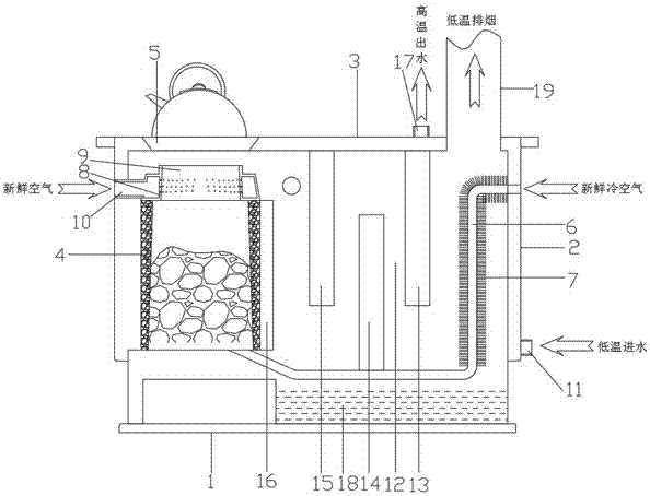
[0021] Embodiment 1, as attached figure 1 As shown, an energy-saving heating furnace includes: a bottom plate 1, a box body 2 and a furnace surface 3; the box body 2 is installed on the top of the bottom plate 1; the top of the box body 2 is covered by the furnace surface 3; the box body 2 A furnace body 4 is arranged inside; the furnace surface 3 is provided with a stove 5 corresponding to the top of the furnace body 4; a waste heat utilization warehouse 12 is also arranged in the box body 2; the bottom of the furnace body 4 is connected with the air supply pipe 6; through the The air supply pipe supplies fresh cold air to the furnace body; the furnace mouth 8 above the furnace body 4 is provided with a conical fire gathering port 9; ; The waste heat utilization chamber 12 is provided with a heat absorption pipe 11; the heat absorption pipe 11 is sequentially connected to the waste heat absorption plate 13, the low temperature heat absorption plate 14, the medium temperature ...
Embodiment 2
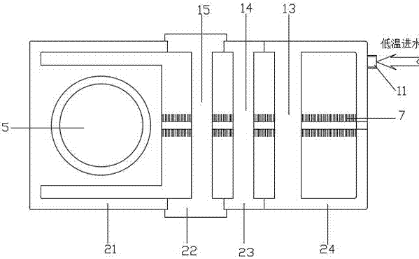
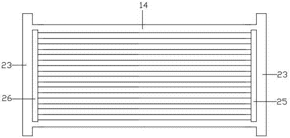
[0024] Embodiment 2, as attached figure 2 As shown; the overall exterior of the box body 2 is also provided with an outsourcing water layer; the inside of the outsourcing water layer is divided into high-temperature circulating water zone 21, medium-temperature circulating water zone 22, and low-temperature circulating water zone 23 from left to right through welding and the waste heat circulating water zone 24; the high temperature circulating water zone 21 communicates with the high temperature heat absorbing jacket 16; the medium temperature circulating water zone 22 communicates with the medium temperature heat absorbing plate 15; the low temperature circulating water zone 23 communicates with the low temperature heat absorbing The water pan 14 is in communication; the waste heat circulating water area 24 is in communication with the waste heat absorbing water plate 13; the heat absorption pipe 11 injects low-temperature cold water into the waste heat circulating water are...
PUM
 Abstract
Description
Claims
Application Information
 - R&D Engineer
- R&D Manager
- IP Professional
- Industry Leading Data Capabilities
- Powerful AI technology
- Patent DNA Extraction
Browse by: Latest US Patents, China's latest patents, Technical Efficacy Thesaurus, Application Domain, Technology Topic, Popular Technical Reports.
© 2024 PatSnap. All rights reserved.Legal|Privacy policy|Modern Slavery Act Transparency Statement|Sitemap|About US| Contact US: help@patsnap.com