Fan blade

A fan blade and blade technology is applied in the field of fan structure design to achieve the effect of suppressing eddy current detachment and reducing backflow

Inactive Publication Date: 2017-10-13
ANHUI ZHILIANG INVESTMENT GRP
View PDF0 Cites 2 Cited by
  • Summary
  • Abstract
  • Description
  • Claims
  • Application Information

AI Technical Summary

Problems solved by technology

[0006] Aiming at the noise problem of the existing fan, the present invention intends to design a fan blade, which can reduce the noise

Method used


Image

  • Fan blade

Examples


Embodiment 1

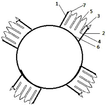
[0014] A small single-rotor fan for household use has 12 incisions on the blade, the incisions penetrate the front and rear surfaces of the blade, the incision closest to the leading edge of the fan blade is located at 1 / 10 arc length from the leading edge of the fan blade, and the incision closest to the trailing edge of the fan blade Located 1 / 10 of the arc length from the trailing edge of the fan blade, between the two rows of slits 1 / 10 of the arc length from the leading edge and the trailing edge of the fan blade, several slits are arranged in sequence, with a distance of 10mm between the slits, and the lower ends of the slits are closed at the distance from At 8mm from the lower edge of the blade, the upper end of the incision is opened on the upper edge of the blade; the inclination angle of the incision against the wind is 65°, and the incision width is 3mm.

Embodiment 2

[0016] For household counter-rotating double-rotor fans, the front and rear blades are arranged in pairs, and the cutouts are arranged on each blade as in Example 1.

Embodiment 3

[0018] For a small single-rotor fan for household use, the blades are arranged with cutouts as in Example 1. In addition, the upper edge of the fan blades is set in a zigzag shape with a tooth width of 5 mm and a tooth pitch of 6 mm.


PUM

PropertyMeasurementUnit
Tooth widthaaaaaaaaaa
Tooth pitchaaaaaaaaaa

Abstract

The invention discloses a fan blade. The blade includes several cutouts. The cutouts penetrate the front and rear surfaces of the blade. The cutout closest to the front edge of the fan blade is located at a distance of 1 / 10 arc length from the front edge of the fan blade and a distance from the tail edge of the fan blade. The nearest incision is located 1 / 10 of the arc length from the trailing edge of the fan blade, between the two rows of incisions 1 / 10 of the arc length from the leading edge and the trailing edge of the fan blade, several incisions are arranged in sequence, the distance between the two incisions is 10mm, and the lower end of the incision It is closed at 8mm away from the lower edge of the blade, and the upper end of the slit is opened at the upper edge of the blade; the inclination angle of the slit facing the incoming wind is 65°, and the slit is 3mm wide. The upper edge of the fan blade is zigzag, with a tooth width of 5mm and a pitch of 6mm. By changing the design of the fan blade and the upper edge, the penetrating cut on the blade and the zigzag design on the upper edge affect the static characteristics of the fan and the flow characteristics of the surrounding air. Due to the design of the slit, the static pressure distribution on the blade is changed, and the backflow at the leading edge and tip of the corresponding slit blade is suppressed and reduced, thereby suppressing the occurrence of vortex shedding and achieving the effect of noise reduction.

Description

technical field [0001] The invention relates to a structural design of a fan, which belongs to the field of fluid machinery. Background technique [0002] A fan is a machine that uses the mechanical energy of the impeller or other forms of rotor rotation to increase the gas pressure and discharge the gas. [0003] Equipment, it is widely used in household, petrochemical, metallurgy, mining, aerospace and energy and other fields. As a type of fan, the small axial flow fan is small in size and is usually used for heat dissipation and ventilation of small products such as home appliances, computers, servers, etc. The main performance is mainly reflected in two aspects: ventilation performance and noise. [0004] Fan noise is the most important noise source in many devices. With the popularization of home appliances such as computers, fans, and air conditioners in offices and homes, people are paying more and more attention to the impact of noise on people. If users are expose...

Claims


Application Information

Patent Timeline
IPC IPC(8): F04D29/38F04D29/66
CPCF04D29/384F04D29/663F04D29/667
Inventor 刘和勇
Owner ANHUI ZHILIANG INVESTMENT GRP
Why Eureka
Try Eureka