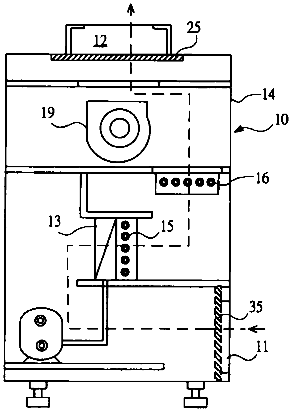
A gas purification device based on composite mesoporous fibers
A technology of gas purification device and composite fiber, which is applied in the direction of gas treatment, transportation and packaging, chemical instruments and methods, etc., can solve the problems of limited purification capacity and low purification efficiency, and achieve the effect of high purification efficiency
- Summary
- Abstract
- Description
- Claims
- Application Information
AI Technical Summary
Problems solved by technology
Method used
Image
Examples
Embodiment 1
[0031] The TiO 2 Preparation steps of composite fibers:
[0032] Step 1, take 5ml of glacial acetic acid and 8ml of absolute ethanol in a conical flask as a solvent, then weigh 0.7g of polyvinyl perrolidone and add it to the above mixed solution, and stir evenly at room temperature;
[0033] Step 2, slowly add 4.2 g of butyl titanate to the above mixed solution, continue to stir, then weigh 1.4 g of diisopropyl azodicarboxylate as a foaming agent, and continue to stir;
[0034] Step 3, then add appropriate amount of WCl 6 , AgNO 3 , ferric chloride, continue to stir for 2h, obtain the precursor spinning solution;
[0035] Step 4, put the above-mentioned precursor spinning solution to rest, measure 9ml and inject it into a plastic needle tube, and put it on a micro-injection pump, and set the injection speed to 1.3ml / h. The metal needle is used as the electrospinning anode, and the wire mesh is used as the cathode of the receiving material. The distance between the anode an...
Embodiment 2
[0038] The TiO 2 Preparation steps of composite fibers:
[0039] Step 1, take 9ml of glacial acetic acid and 8ml of absolute ethanol in a conical flask as a solvent, then weigh 0.7g of polyvinyl perrolidone and add it to the above mixed solution, and stir evenly at room temperature;
[0040] Step 2, slowly add 4.2 g of butyl titanate to the above mixed solution, continue to stir, then weigh 1.4 g of diisopropyl azodicarboxylate as a foaming agent, and continue to stir;
[0041] Step 3, then add appropriate amount of WCl 6 , AgNO 3 , ferric chloride, continue to stir for 2h, obtain the precursor spinning solution;
[0042] Step 4, put the above-mentioned precursor spinning solution to rest, measure 6ml and inject it into a plastic needle tube, and place it on a micro-injection pump, and set the injection speed to 1ml / h. The metal needle is used as the electrospinning anode, and the wire mesh is used as the cathode of the receiving material. The distance between the anode an...
Embodiment 3
[0045] The TiO 2 Preparation steps of composite fibers:
[0046] Step 1, take 6ml of glacial acetic acid and 8ml of absolute ethanol in a conical flask as a solvent, then weigh 0.7g of polyvinyl perrolidone and add it to the above mixed solution, and stir evenly at room temperature;
[0047] Step 2, slowly add 4.2 g of butyl titanate to the above mixed solution, continue to stir, then weigh 1.4 g of diisopropyl azodicarboxylate as a foaming agent, and continue to stir;
[0048] Step 3, then add appropriate amount of WCl 6 , AgNO 3 , ferric chloride, continue to stir for 2h, obtain the precursor spinning solution;
[0049] Step 4, put the above-mentioned precursor spinning solution to rest, measure 6ml and inject it into a plastic needle tube, and place it on a micro-injection pump, and set the injection speed to 1ml / h. The metal needle is used as the electrospinning anode, and the wire mesh is used as the cathode of the receiving material. The distance between the anode an...
PUM
 Abstract
Description
Claims
Application Information
 - Generate Ideas
- Intellectual Property
- Life Sciences
- Materials
- Tech Scout
- Unparalleled Data Quality
- Higher Quality Content
- 60% Fewer Hallucinations
Browse by: Latest US Patents, China's latest patents, Technical Efficacy Thesaurus, Application Domain, Technology Topic, Popular Technical Reports.
© 2025 PatSnap. All rights reserved.Legal|Privacy policy|Modern Slavery Act Transparency Statement|Sitemap|About US| Contact US: help@patsnap.com

