Impedance detecting device and method for in-vivo detection of spongioblastoma boundary and application of device
A malignant glioma and detection device technology, which is applied in the field of electrical impedance detection devices for in vivo exploration of malignant glioma boundaries, can solve the problems of inability to distinguish tumor tissue, expensive MRI equipment, and high photosensitizer content, so as to reduce tumor recurrence. rate, improve the quality of surgical treatment, and preserve the effect of neurological function
- Summary
- Abstract
- Description
- Claims
- Application Information
AI Technical Summary
Problems solved by technology
Method used
Image
Examples
Embodiment 1 4
[0041] Embodiment 1 Four-probe electrical impedance detection device
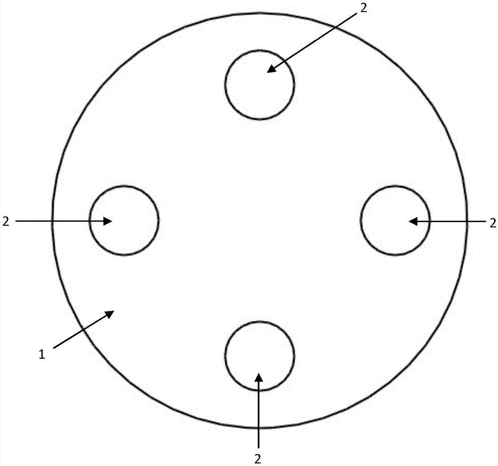
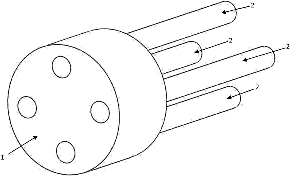
[0042] Such as Figure 1-2 as shown, figure 1 is the front view of the four-probe electrical impedance detection device, figure 2 Schematic diagram of the structure of the four-probe electrical impedance detection device. An electrical impedance detection device, comprising an electrode orifice 1 and four electrode probes 2, characterized in that the electrode orifice 1 is cylindrical, the diameter of the electrode orifice 1 is 3mm, and the four electrode probes 2 are separated from the center Points 0.98 mm in circumference are evenly arranged in the electrode orifice plate, and the electrode probe 2 is made of 925 silver wire with a diameter of 3 mm. One end of the electrode probe 2 is welded and fixed to the upper surface of the electrode orifice plate 1, and the other end is connected to the electrode orifice plate. The lower surface of the orifice plate 1 is pierced. The electrode probe includes t...
Embodiment 2
[0043] Embodiment 2 Ring electrical impedance detection device
[0044] Such as Figure 6-7 as shown, Figure 6 is the front view of the ring electrical impedance detection device, Figure 7 It is a schematic diagram of the structure of the ring electrical impedance detection device. An electrical impedance detection device, comprising an electrode hole plate 1, four electrode probes 2, and wires 3 respectively connected to the four electrode probes 2, the four electrode probes 2 are concentrically nested in the electrode hole plate 1 The first electrode 4, the second electrode 5, the third electrode 6 on the surface, and the fourth electrode 7 located at the center of the electrode hole plate 1; the first electrode 4, the second electrode 5, and the third electrode 6 are annular , whose radii are 2.4mm, 1.65mm, and 0.9mm in turn. The width of the first electrode 4 , the second electrode 5 and the third electrode 6 is 0.2 mm. The diameter of the fourth electrode 7 is 0.3 ...
Embodiment 3 4
[0045] Embodiment 3 four-probe impedance measurement experiment
[0046] 1 Impedance measurement experiment preparation
[0047] (1) Establishment of impedance measurement platform
[0048] The used in-body impedance measurement platform mainly includes: four-probe measurement electrodes based on the four-electrode method, an electrode hole plate for fixing the probes, and a clamping mechanism. Such as figure 1 and figure 2 As shown, the electrical impedance detection device includes an electrode hole plate and four electrode probes, wherein the material of the measuring electrode probe is 925 silver (or S925), that is, the silver content is not less than 92.5%. Compared with pure silver, S925 adds 7.5% of other metals, which makes it have better hardness, better shaping, and good oxidation resistance and electrical conductivity. The electrode hole plate used to fix the probe is made of PCB substrate material. On the one hand, for the convenience of processing, because th...
PUM
 Abstract
Description
Claims
Application Information
 - Generate Ideas
- Intellectual Property
- Life Sciences
- Materials
- Tech Scout
- Unparalleled Data Quality
- Higher Quality Content
- 60% Fewer Hallucinations
Browse by: Latest US Patents, China's latest patents, Technical Efficacy Thesaurus, Application Domain, Technology Topic, Popular Technical Reports.
© 2025 PatSnap. All rights reserved.Legal|Privacy policy|Modern Slavery Act Transparency Statement|Sitemap|About US| Contact US: help@patsnap.com


