
Vertical compressor suitable for high-temperature gas media

A high-temperature gas and compressor technology, which is applied to liquid variable-capacity machinery, mechanical equipment, and variable-capacity pump components.

Active Publication Date: 2017-10-10
JIANGSU XIYA PETROCHEM EQUIP
View PDF12 Cites 0 Cited by
  • Summary
  • Abstract
  • Description
  • Claims
  • Application Information

AI Technical Summary

Problems solved by technology

Vertical piston compressor is a kind of compressor. The piston and crank are connected by crosshead and connecting rod. When the high temperature (≤400℃) gas medium is compressed in the cylinder, it is necessary to install a suitable compressor on the compressor. Cooling mechanism, labyrinth compressors under normal working conditions are usually cooled by circulating water, that is, water cooling channels are set on the cylinder block and crosshead slide to realize cooling of the cylinder block and crosshead, but under high temperature conditions, the cylinder cannot be water cooled method, and the piston rod and the crosshead need to be cooled, the existing compressor structure cannot meet the cooling requirements

Method used


Image

  • Vertical compressor suitable for high-temperature gas media
  • Vertical compressor suitable for high-temperature gas media
  • Vertical compressor suitable for high-temperature gas media

Examples


Embodiment Construction

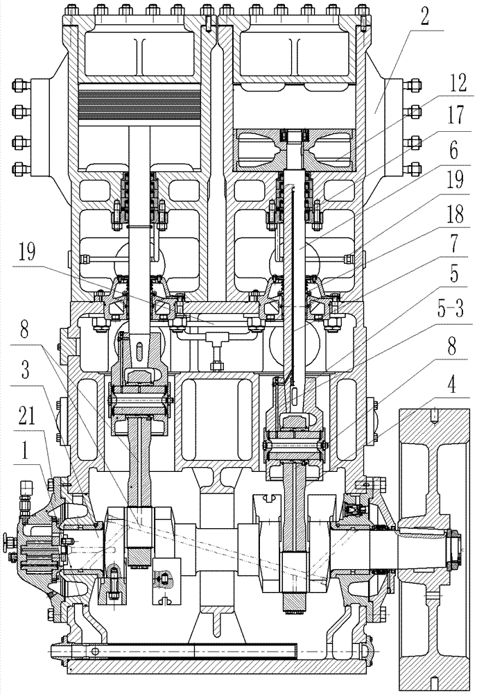
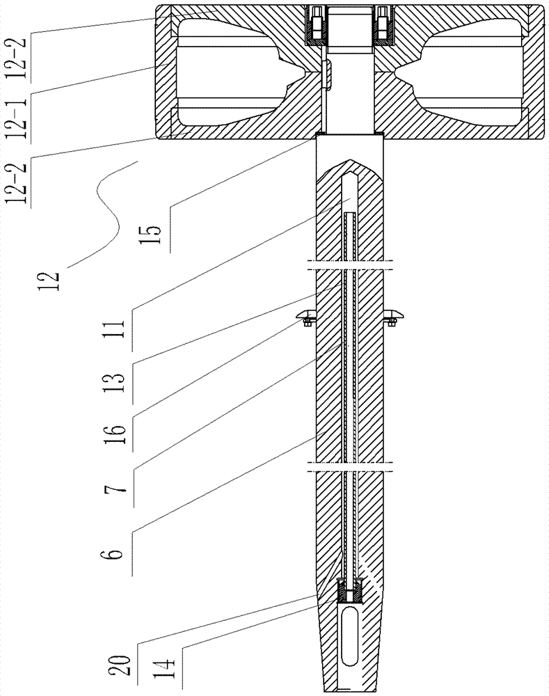
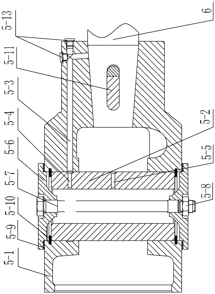
[0022] See Figure 1 to Figure 7 As shown, a vertical compressor suitable for high-temperature gas medium includes a crankcase 1 and a cylinder 2. A crankshaft 3 is arranged in the crankcase 1. The crankshaft 3 is connected to one end of a connecting rod 4, and the other end of the connecting rod 4 passes through a crosshead structure. 5 is connected to the piston rod 6, the piston head 12 at the end of the piston rod 6 is set in the cylinder body of the cylinder 2, the crankshaft 3 and the connecting rod are provided with a first oil passage 8 connected to each other, and the inlet of the first oil passage 8 is connected to the oil pump 21, The crosshead structure 5 includes a crosshead body 5-1 and a crosshead pin 5-2 installed on the crosshead body 5-1. The inside of the crosshead pin 5-2 is a hollow cavity, and the crosshead body 5-1 is provided with a first The second oil passage 5-3, the first oil hole 5-4 connecting the hollow cavity and the second oil passage 5-3 is op...


PUM


Abstract

The invention relates to the technical field of compressor structures, in particular to a vertical compressor suitable for high-temperature gas media, and accordingly integral compressor cooling can be conveniently achieved. The vertical compressor comprises a crank case and an air cylinder. A crankshaft is connected with a piston rod through a connecting rod and a cross-shaped head structure. A communication first oil path is arranged in the crankshaft and the connecting rod. An inlet of the first oil path is connected with an oil pump. The cross-shaped head structure comprises a cross-shaped head body and a cross-shaped head pin arranged on the cross-shaped head body. A hollow cavity is formed in the cross-shaped head pin. A second oil path is arranged in the cross-shaped head body. The cross-shaped head pin is provided with a first oil hole communicating with the hollow cavity and the second oil path, and a second oil hole communicating with the hollow cavity and an outlet of the first oil path. Sealing covers are arranged at the two ends of the cross-shaped head pin, a third oil path communicating with the second oil path is arranged in the piston rod, and a hollow oil return pipe communicating with the third oil path is arranged in the middle of the piston rod. An oil inlet and an oil outlet are formed in the outer wall of a cylinder body of the air cylinder. An oil cooling channel communicating with the oil inlet and the oil outlet is arranged in the cylinder body of the air cylinder.

Description

technical field [0001] The invention relates to the technical field of compressor structure, in particular to a vertical compressor suitable for high-temperature gas medium. Background technique [0002] Compressor is a driven fluid machine that upgrades low-pressure gas to high-pressure gas, and can be divided into piston compressors, screw compressors, centrifugal compressors, linear compressors, etc. Vertical piston compressor is a kind of compressor. The piston and crank are connected by crosshead and connecting rod. When the high-temperature (≤400℃) gas medium is compressed in the cylinder, it is necessary to install a suitable compressor on the compressor. Cooling mechanism, labyrinth compressors under normal working conditions are usually cooled by circulating water, that is, water cooling channels are installed on the cylinder block and crosshead slide to realize cooling of the cylinder block and crosshead, but under high temperature conditions, the cylinder cannot b...

Claims


Application Information

Patent Timeline
IPC IPC(8): F04B37/18F04B39/06
CPCF04B37/18F04B39/06
Inventor 徐晓梅黄顺良陶加勇
Owner JIANGSU XIYA PETROCHEM EQUIP
Learn More