Lid and container
A lid and container technology, applied in the field of drinking utensils, can solve the problems of small water storage space, difficult to overcome pressure, inconvenient use and operation, etc., to achieve the effect of facilitating cooling and ensuring the partition effect
- Summary
- Abstract
- Description
- Claims
- Application Information
AI Technical Summary
Problems solved by technology
Method used
Image
Examples
Example Embodiment
[0054] Example 1
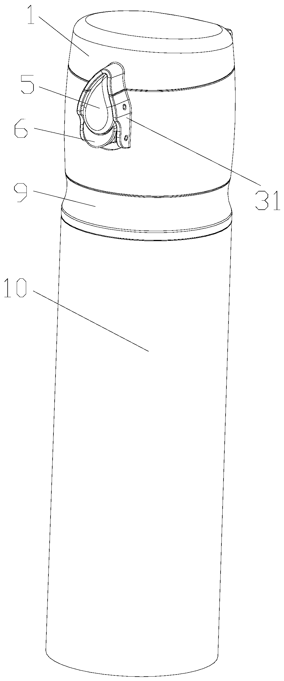
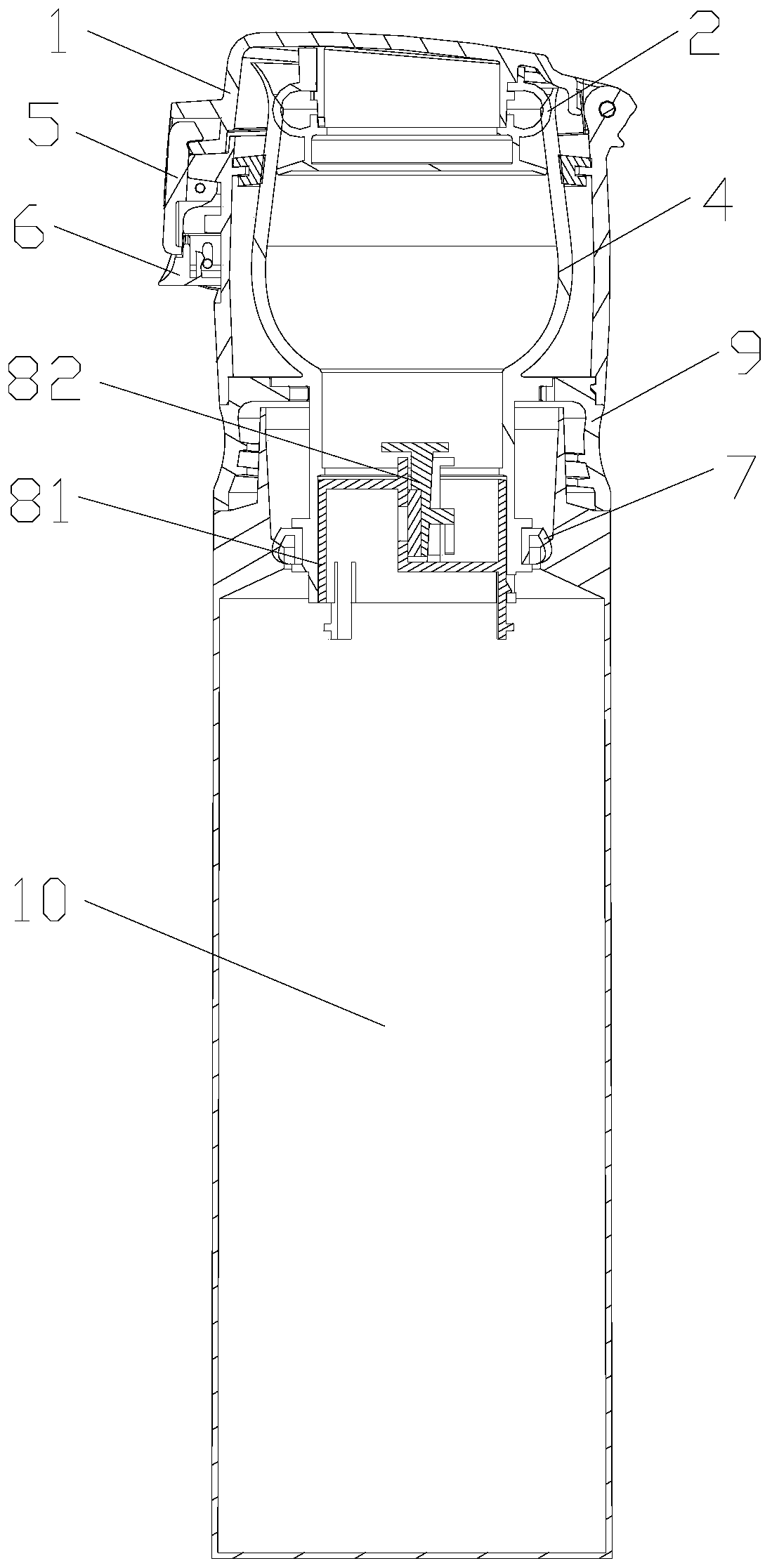
[0055] Such as Figure 1 to Figure 3 The container shown includes a lid and a second cup body 10 that are connected to each other. The lid and the second cup body 10 can be directly connected by a snap connection or a threaded connection. Of course, the lid and the second cup body 10 It can also be connected by a connecting ring 9.
[0056] The cover includes an upper cover 1, a first cup body 4, and a valve 8. The upper cover 1 is provided on the top of the first cup body 4, the valve 8 is provided in the first cup body 4, and the valve 8 includes a valve The valve body 81 is provided with a through hole 812 for communicating the inside and outside of the first cup 4, the valve 82 is movably arranged on one side of the through hole 812, and the valve 82 is in the through hole 812. A limit structure is provided in the opening direction.
[0057] In order to increase the heat dissipation performance of the first cup body and at the same time prevent the first cup ...
Example Embodiment
[0068] Example 2
[0069] This embodiment is basically the same as the first embodiment, except that there are differences in the sliding structure of the valve 82 and the valve body 81, such as Figure 14 to Figure 16 As shown, in the second embodiment, the through grooves 821 on both sides of the valve 82 are eliminated, and the guide strips 813 on the inner wall of the valve body are also eliminated. Only the vertical plate of the partition 811 and the positioning strips 814 have an effect on the valve 82. Roughly guiding, this can already meet the normal opening and closing requirements of the valve 82; due to the limited volume of the valve body, it is not easy to process the structure on the inner wall of the valve body. However, this embodiment makes the valve body structure more streamlined and more convenient to manufacture , Thereby saving costs.
Example Embodiment
[0070] Example 3
[0071] Such as Figure 1 to Figure 3 The container shown includes a lid and a second cup body 10 that are connected to each other. The lid and the second cup body 10 can be directly connected by a snap connection or a threaded connection. Of course, the lid and the second cup body 10 It can also be connected by a connecting ring 9.
[0072] The cover includes an upper cover 1, a first cup body 4, and a valve 8. The upper cover 1 is provided on the top of the first cup body 4, the valve 8 is provided in the first cup body 4, and the valve 8 includes a valve The valve body 81 is provided with a through hole 812 for communicating the inside and outside of the first cup 4, the valve 82 is movably arranged on one side of the through hole 812, and the valve 82 is in the through hole 812. A limit structure is provided in the opening direction.
[0073] In order to increase the heat dissipation performance of the first cup body and at the same time prevent the first cup ...
PUM
 Abstract
Description
Claims
Application Information
 - R&D
- Intellectual Property
- Life Sciences
- Materials
- Tech Scout
- Unparalleled Data Quality
- Higher Quality Content
- 60% Fewer Hallucinations
Browse by: Latest US Patents, China's latest patents, Technical Efficacy Thesaurus, Application Domain, Technology Topic, Popular Technical Reports.
© 2025 PatSnap. All rights reserved.Legal|Privacy policy|Modern Slavery Act Transparency Statement|Sitemap|About US| Contact US: help@patsnap.com


