
Fixing device for machining bathroom equipment

A technology for fixing devices and equipment, which is applied to workbenches, manufacturing tools, clamps, etc., can solve the problems of reducing the practicability of fixing devices for bathroom equipment processing, not having automatic clamping, and prolonging the working time of users, and achieves enhanced Practicality, reduced working time, increased friction effect

Inactive Publication Date: 2017-10-10
湖州裕尚卫浴有限公司
View PDF1 Cites 3 Cited by
  • Summary
  • Abstract
  • Description
  • Claims
  • Application Information

AI Technical Summary

Problems solved by technology

[0003] When processing sanitary equipment, it is necessary to use a fixing device for processing sanitary equipment. For example, a Chinese patent discloses "fixing device in the process of forming and processing sanitary equipment" (patent number: CN204772973U). This patent includes a pneumatic component directly above the base , a pneumatic rod is set between the pneumatic part and the base, a support frame is set on the base, two screw screws and two support shafts are set above the support frame, a threaded column is set directly below the support plate, and a threaded column is fitted on the threaded column. The positioning seat, the top of one of the positioning seats on each threaded column is in contact with the bottom end of the support plate, the two ends of each support shaft are fitted with a positioning sleeve, and the lead screw is fitted with a guide sleeve, The guide sleeves are respectively fixed to the top ends of the corresponding support plates. A forming seat is provided between the screw screws. A groove is provided on the top of the forming seat, and a threaded hole is provided on the side wall of the forming seat. This device strengthens the connection tightness of the structure, It makes its fixing more firm, can guarantee its quality when the bathroom equipment is molded, reduces the generation of waste products, and reduces the production cost, but the existing fixing device for bathroom equipment processing does not have the function of automatic clamping, which prolongs the working time of the user , reducing the practicability of fixtures for bathroom fixtures

Method used


Image

  • Fixing device for machining bathroom equipment
  • Fixing device for machining bathroom equipment
  • Fixing device for machining bathroom equipment

Examples


Embodiment Construction

[0018] (In the description of the present invention, it is to be understood that the terms "center", "longitudinal", "transverse", "length", "width", "thickness", "upper", "lower", "front", Orientation indicated by "back", "left", "right", "vertical", "horizontal", "top", "bottom", "inner", "outer", "clockwise", "counterclockwise", etc. Or the positional relationship is based on the orientation or positional relationship shown in the drawings, which is only for the convenience of describing the present invention and simplifying the description, and does not indicate or imply that the referred equipment or elements must have a specific orientation, be constructed and operated in a specific orientation , and therefore cannot be construed as a limitation of the present invention.

[0019] In addition, the terms "first" and "second" are used for descriptive purposes only, and cannot be interpreted as indicating or implying relative importance or implicitly specifying the quantity ...


PUM


Abstract

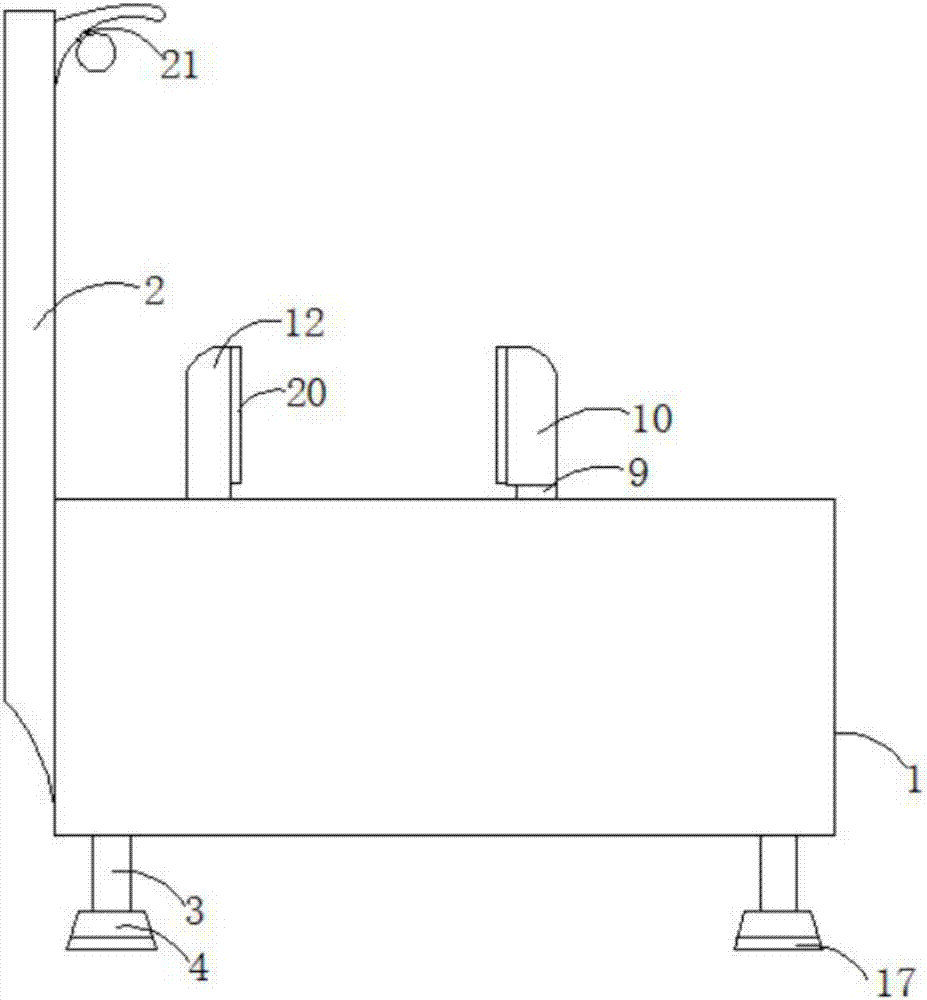
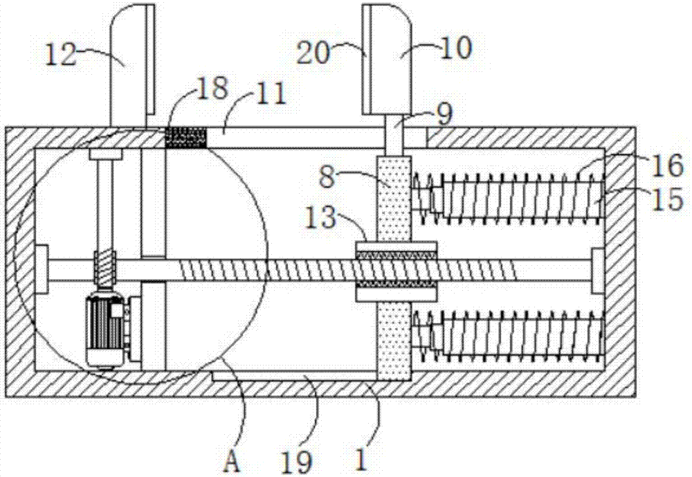
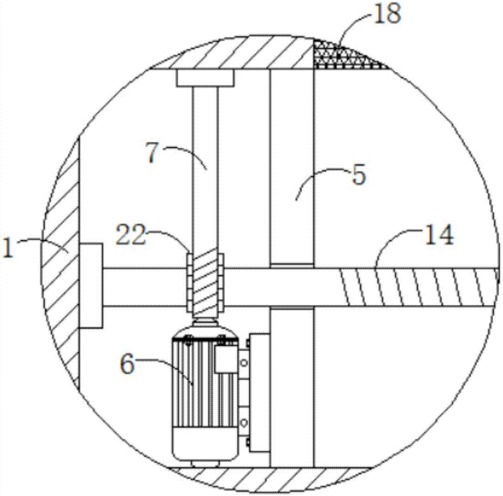
The invention discloses a fixing device for sanitary equipment processing, comprising a box body, the left side of the box body is fixedly connected with a fixing column, both sides of the bottom of the box body are fixedly connected with fixing legs, and the fixing legs The bottom is fixedly connected with a base, the inner cavity of the box body is fixedly connected with a fixing plate, and the left side of the bottom of the fixing plate is fixedly connected with a motor. The present invention is provided with box body, fixed column, fixed leg, base, fixed plate, motor, worm, slide plate, slider, movable claw, opening, fixed claw, screw sleeve, screw rod, telescopic rod, spring, anti-skid pad, The cooperation of the anti-collision pad, the chute, the cushion, the lighting lamp and the worm wheel solves the problem that the existing fixtures for processing sanitary equipment do not have the function of automatic clamping. The utility model has the advantages of reducing the working time of the user and enhancing the practicability of the fixing device for sanitary equipment processing.

Description

technical field [0001] The invention relates to the technical field of a fixing device for processing sanitary equipment, in particular to a fixing device for processing sanitary equipment. Background technique [0002] Sanitary ware literally means sanitation and bathing. Sanitary ware is commonly known as a toilet mainly used for bathing. It is a space and supplies for daily hygiene activities such as defecation, bathing, and washing. [0003] When processing sanitary equipment, it is necessary to use a fixing device for processing sanitary equipment. For example, a Chinese patent discloses "fixing device in the process of forming and processing sanitary equipment" (patent number: CN204772973U). This patent includes a pneumatic component directly above the base , a pneumatic rod is set between the pneumatic part and the base, a support frame is set on the base, two screw screws and two support shafts are set above the support frame, a threaded column is set directly below ...

Claims


Application Information

Patent Timeline
Patent Type & Authority Applications(China)
IPC IPC(8): B25B5/10B25B5/02B25H1/10
CPCB25B5/102B25B5/006B25B5/02B25H1/10
Inventor 陆惠明
Owner 湖州裕尚卫浴有限公司
Learn More