
Novel bridge maintenance equipment

A technology for maintaining equipment and bridges, which is applied in bridge construction, bridge maintenance, bridges, etc. It can solve problems such as shortened service life, air pollution, and reduced service life of power supply lines, so as to prevent rapid aging, increase electricity safety, and increase The effect of service life

Inactive Publication Date: 2017-10-03
斯幼云
View PDF1 Cites 0 Cited by
  • Summary
  • Abstract
  • Description
  • Claims
  • Application Information

AI Technical Summary

Problems solved by technology

[0002] Electrified maintenance equipment is often used in the bridge maintenance process. However, in some bridge constructions, there are fewer preset power supply sockets, which cannot meet the power supply connection requirements for maintenance equipment. In addition, the existing bridge power supply sockets are all fixed settings. When construction and maintenance When the location is far away from the power supply base, the power supply connection of the electrification maintenance equipment is relatively short, so that the power supply connection cannot be completed. In the existing similar problems, one or more terminal boards are generally used to extend the connection to achieve electrification. The purpose of plugging power supply for maintenance equipment. However, after multiple terminal boards are connected, the power supply wire has a certain length, which is extremely inconvenient when rewinding. If it is not rewound in time after use, it will easily cause damage to the skin of the power supply wire and shorten the service life. At the same time, there are large hidden dangers of power supply. In addition, due to the different powers of maintenance equipment in construction, transformers are generally installed to meet the power supply requirements of different types of maintenance equipment. However, these transformers are generally installed outside without any protective measures, easily damaged
[0003] With the continuous improvement of living standards, the number of people who own small electrified maintenance equipment is constantly increasing. Small electrified maintenance equipment is generally powered by gasoline. As we all know, carbon dioxide, carbon monoxide and some sulfur compounds after gasoline combustion can cause atmospheric pollution Pollution, with the increase of electrification maintenance equipment, the problem of air pollution is becoming more and more serious, but with the increase of people's environmental awareness, people pay more and more attention to new energy electrification maintenance equipment, and pure electric electrification maintenance equipment has become a new energy electrification maintenance The main force of the equipment, the pure electric electrification maintenance equipment does not need to use gasoline and diesel oil, therefore, there is almost no pollution to the atmosphere, the power of the pure electric electrification maintenance equipment comes from the battery, and the battery needs to be powered to provide power for the electrification maintenance equipment, power supply The pile can supply power to the electric electrification maintenance equipment, and a transformer is usually installed on the power supply pile, and the transformer can adjust the power supply parameters according to the demand, such as the power supply time, etc. Various factors can easily damage the transformer, and once the transformer fails, it will be troublesome to repair and the cost will be high. Electrified maintenance equipment is rolled and easily aged, especially outdoors. Therefore, the service life of the power supply line will be reduced, and it will also bring safety hazards

Method used


Image

  • Novel bridge maintenance equipment
  • Novel bridge maintenance equipment
  • Novel bridge maintenance equipment

Examples


Embodiment Construction

[0021] All features disclosed in this specification, or steps in all methods or processes disclosed, may be combined in any manner, except for mutually exclusive features and / or steps.

[0022] Any feature disclosed in this specification (including any appended claims, abstract and drawings), unless expressly stated otherwise, may be replaced by alternative features which are equivalent or serve a similar purpose. That is, unless expressly stated otherwise, each feature is one example only of a series of equivalent or similar features.

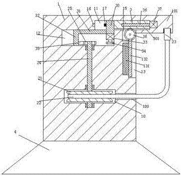
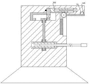
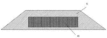
[0023] Such as Figure 1-4As shown, a new type of bridge maintenance equipment of the present invention includes a body 1, a top plate 101 is arranged on the upper right end of the body 1, and a clamping groove 14 with a notch downward is arranged in the lower end surface of the top plate 101. 1 is provided with a winding groove 10 and a communication hole 100 communicating with the winding groove 10, a steering shaft 24 is turnably installed...


PUM


Abstract

The invention discloses novel bridge maintenance equipment. The novel bridge maintenance equipment comprises a machine body, wherein a right upper end of the machine body is provided with a top plate; a coiling groove and a communication hole communicating with the coiling groove are formed in the machine body; a steering shaft is arranged in the coiling groove in a steerable way; a reel is fixedly arranged on the steering shaft; the reel is wound with a cable; a first sliding chute extending into the top plate is formed in the machine body; a sliding plate is arranged in the first sliding chute in a leftward / rightward sliding way; a second sliding chute which is positioned below the first sliding chute and communicates with the first sliding chute is formed in the machine body; a second slide block is arranged in the second sliding chute in a leftward / rightward sliding way; a first slide block is fixedly arranged at a left end of the sliding plate; a lower end of the first slide block extends into the second sliding chute; an armed lever is fixedly connected between a lower end of the first slide block and the second slide block; a first motor is fixedly arranged at the lower end of the first slide block; and first toothed wheels are arranged on the first motor.

Description

technical field [0001] The invention relates to the technical field of bridges, in particular to a novel bridge maintenance equipment. Background technique [0002] Electrified maintenance equipment is often used in the bridge maintenance process. However, in some bridge constructions, there are fewer preset power supply sockets, which cannot meet the power supply connection requirements for maintenance equipment. In addition, the existing bridge power supply sockets are all fixed settings. When construction and maintenance When the location is far away from the power supply base, the power supply connection of the electrification maintenance equipment is relatively short, so that the power supply connection cannot be completed. In the existing similar problems, one or more terminal boards are generally used to extend the connection to achieve electrification. The purpose of plugging power supply for maintenance equipment. However, after multiple terminal boards are connecte...

Claims


Application Information

Patent Timeline
Patent Type & Authority Applications(China)
IPC IPC(8): H01R13/72E01D22/00
CPCH01R13/72E01D22/00
Inventor 斯幼云
Owner 斯幼云
Learn More