An Ellipse Conformation Deviation Estimation Method Based on Tangent Method

A tangent method and ellipse technology, applied in the field of computer vision, can solve problems such as errors that cannot be ignored, simplicity, lack of versatility and accuracy, and the impact of measurement accuracy, so as to avoid coordinate conversion and improve simplicity and accuracy. sexual effect

Active Publication Date: 2020-11-03
HUST WUXI RES INST
View PDF5 Cites 0 Cited by
  • Summary
  • Abstract
  • Description
  • Claims
  • Application Information

AI Technical Summary

Problems solved by technology

Because circular marks are often used in camera calibration, and the existing mark point recognition algorithms often use the center of the ellipse as the center of the circle for calculation. When performing high-precision optical measurement, the error introduced by the approximation process cannot be ignored
The literature "On the accuracy of videometry" (Lenz R and Fritsch D. International Archives of Photogrammetry and Remote Sensing, vol. 27 (B5), pp. 334-345, 1984.) first proposed that when the size of the circular feature is larger, the same as When the camera distance is too short, the eccentricity error of the ellipse will affect the accuracy of the measurement
The document "Systematic Geometric Image Measurement Errors of Circular Object Targets: Mathematical Formulation and Correction" (Ahn S J, Warnecke H J, Kotowski R. Photogrammetric Record, vol.16(93), pp.485-502, 1999.) proposed an elliptical conformation The algebraic calculation method of the deviation, but its method limits the position of the circular feature, and introduces multiple intermediate coordinate systems, and the value of the eccentricity error is given as an approximate result
This method has shortcomings in terms of simplicity, versatility and accuracy

Method used


Image

  • An Ellipse Conformation Deviation Estimation Method Based on Tangent Method
  • An Ellipse Conformation Deviation Estimation Method Based on Tangent Method
  • An Ellipse Conformation Deviation Estimation Method Based on Tangent Method

Examples


Embodiment Construction

[0034] The present invention will be further described below in conjunction with drawings and embodiments. It should be understood that the specific embodiments described here are only used to explain the present invention, but not to limit the present invention. In addition, it should be noted that, for the convenience of description, only some parts related to the present invention are shown in the accompanying drawings but not the whole content. Unless otherwise defined, all technical and scientific terms used herein are related to the technical field of the present invention. The skilled person generally understands the same meaning. The terms used herein are for describing specific embodiments only, and are not intended to limit the present invention.

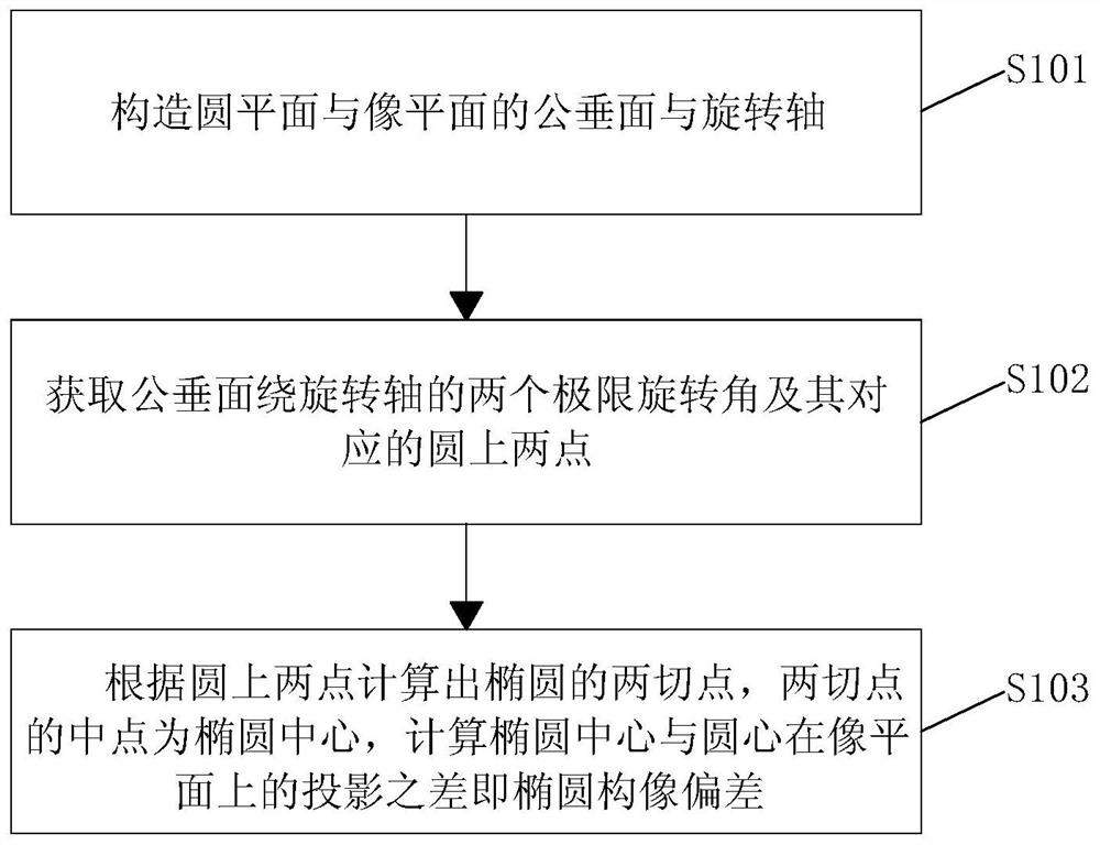
[0035] Please refer to figure 1 as shown, figure 1 The flow chart of the ellipse conformation deviation estimation method based on the tangent method provided by the embodiment of the present invention.

[0036] In thi...


PUM


Abstract

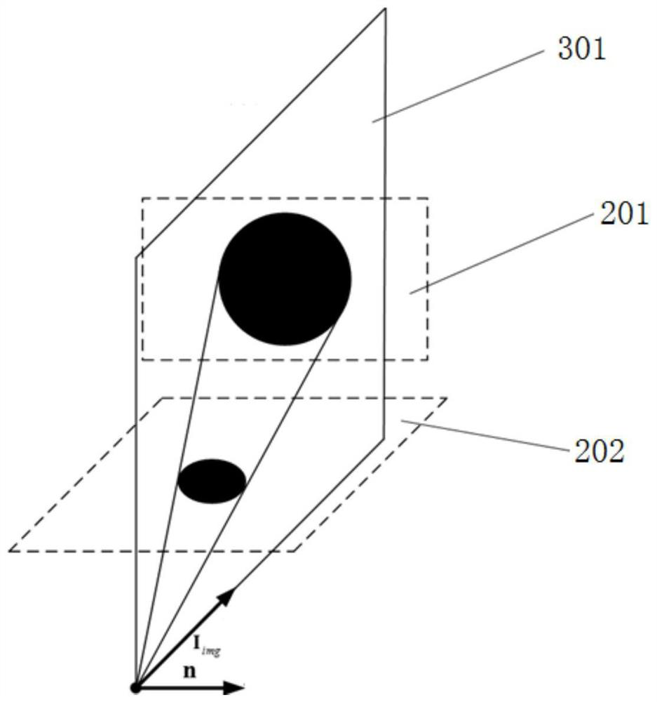
The invention discloses an ellipse imaging deviation estimation method based on a tangent method. The method comprises the following steps: S101) constructing a common vertical plane and a rotation axis of a circle plane and an image plane; S102) obtaining two limit rotation angles of the common vertical plane around the rotation axis and two points on corresponding circles; and S103) calculating two tangency points of an ellipse according to the two points on the corresponding circles, the middle point between the two tangency points being the center of the ellipse, and calculating difference of projection of the ellipse center and the circle center on the image plane, the difference being ellipse imaging deviation. The method has the following advantages: 1) only a world coordinate system and a camera coordinate system are used, thereby preventing coordinate transformation among a plurality of coordinate system, and improving simplicity and precision of the method; and 2) calculation speed and precision depend on extremum calculation speed and accuracy of a rotation angle function, so that the method can meet different precision and speed requirements by adjusting function extremum calculation modes according to different actual application occasions.

Description

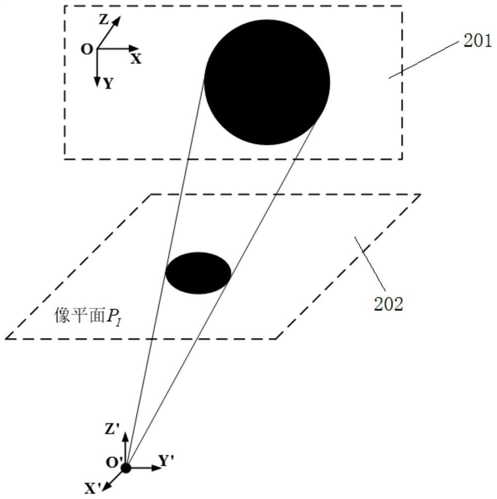
technical field [0001] The invention relates to the field of computer vision, in particular to a method for estimating ellipse conformation deviation based on a tangent method. Background technique [0002] After perspective projection, the circle is projected as an ellipse when the imaging plane is not parallel to the circle plane. However, the center of the projected ellipse is not the projection of the center of the circle on the image plane. The deviation between the two is called the ellipse conformation deviation. Because circular marks are often used in camera calibration, and the existing mark point recognition algorithms often use the center of the ellipse as the center of the circle for calculation. When performing high-precision optical measurement, the error introduced by the approximation process cannot be ignored. The literature "On the accuracy of videometry" (Lenz R and Fritsch D. International Archives of Photogrammetry and Remote Sensing, vol. 27 (B5), pp....

Claims


Application Information

Patent Timeline
Patent Type & Authority Patents(China)
IPC IPC(8): G06T7/60G06T7/80
CPCG06T7/60G06T7/80
Inventor 张旭沈毅君朱利民
Owner HUST WUXI RES INST
Why Eureka
Try Eureka