Al technical title is built by PatSnap Al team. It summarizes the technical point description of the patent document.
A clamping device and wedge-shaped technology, used in measuring devices, instruments, scientific instruments, etc., can solve the problems of small adjustment range, poor working conditions, large dispersion of clamping force, etc., and achieve simple and convenient operation and large clamping range. , The effect of not easy to slip
Active Publication Date: 2020-07-28
中机检测有限公司
View PDF11 Cites 0 Cited by
Summary
Abstract
Description
Claims
Application Information
AI Technical Summary
This helps you quickly interpret patents by identifying the three key elements:
Problems solved by technology
Method used
Benefits of technology
Problems solved by technology
[0004] However, in the process of clamping the sample in the inclined wedge tensile fixture, an axial thrust needs to be applied to the wedge. Under the action of this thrust, the wedge moves in the axial direction, and then exerts a clamping force on the sample. This kind of wedge-type tensile fixture adjusts the installation space of the sample by moving the wedge up and down. The adjustment range is small, and the wedges need to be replaced frequently when the sample size series are greatly different; An axial additional force is generated on the sample, so that the sample can bear the external force before the test begins; at the same time, this manual wedge clamping device clamps slowly, which affects production efficiency; the working conditions are poor, the workers operate frequently, and are prone to fatigue; The discreteness of the clamping force is large, and it is difficult to generate a large clamping force
Method used
Image
Click on the blue label to locate the original text in one second.
Reading with bidirectional positioning of images and text.
Examples
Embodiment Construction
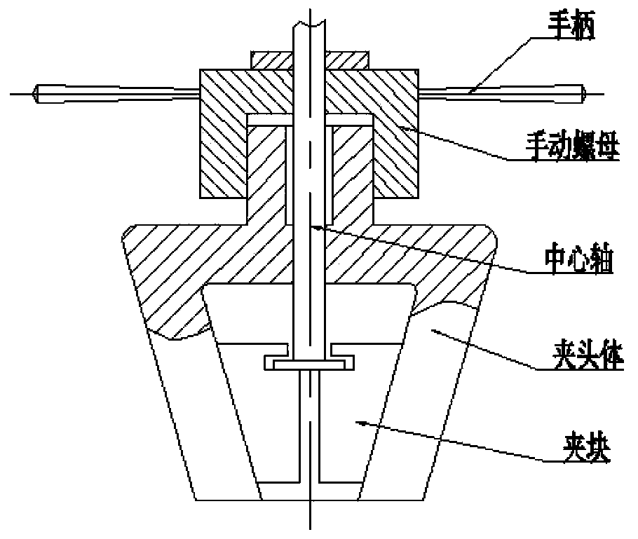
[0038] The invention discloses a flat push wedge-shaped clamping device, which clamps a sample reliably, does not slip, is simple and convenient to operate, has a large clamping range, and the sample does not bear additional axial force during the clamping process, and can also clamp Hold an asymmetric sample.
[0039] The technical solutions in the embodiments of the present invention will be clearly and completely described below in conjunction with the accompanying drawings in the embodiments of the present invention. Obviously, the described embodiments are only a part of the embodiments of the present invention, rather than all the embodiments. Based on the embodiments of the present invention, all other embodiments obtained by those of ordinary skill in the art without creative work shall fall within the protection scope of the present invention.
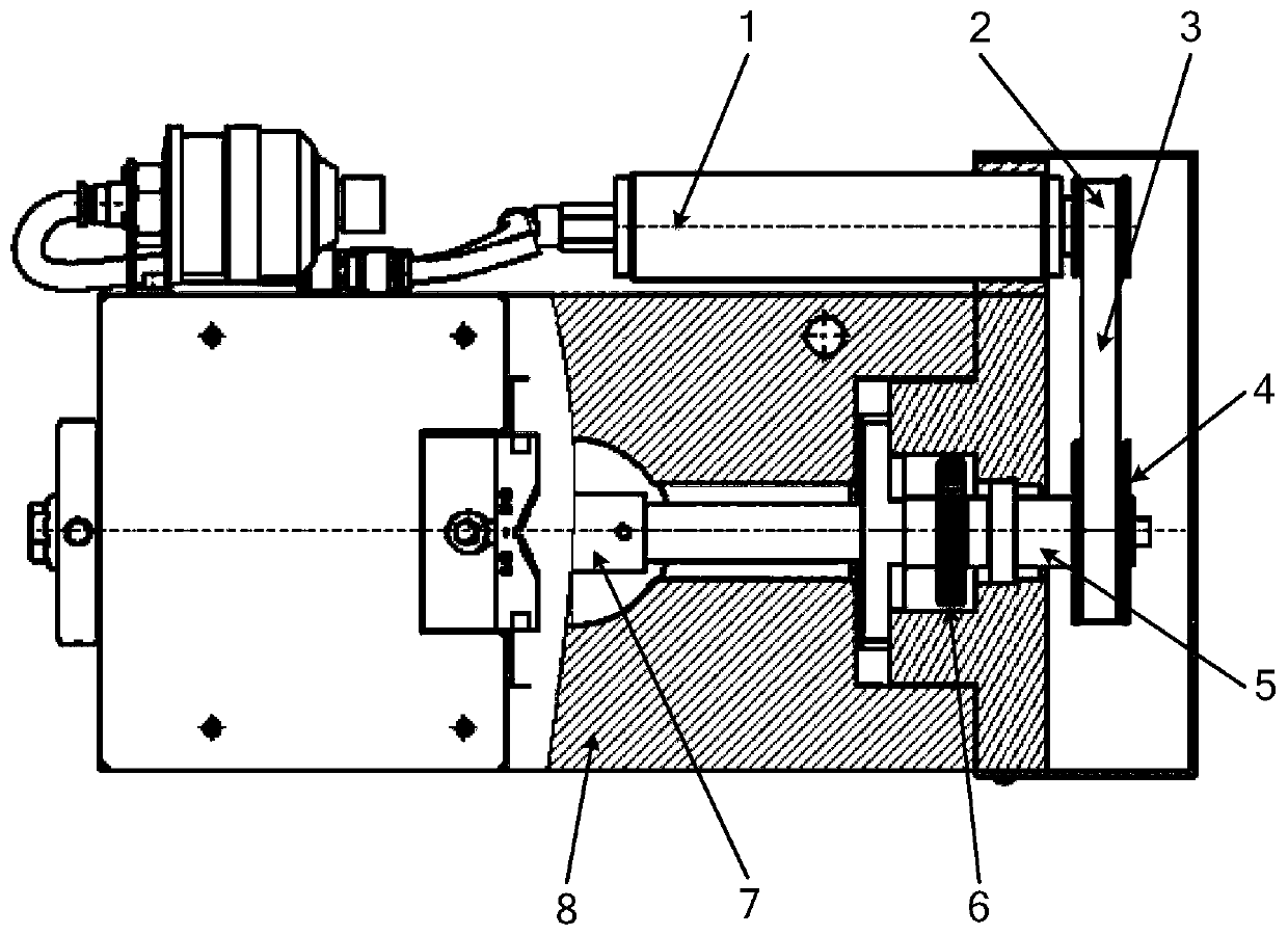
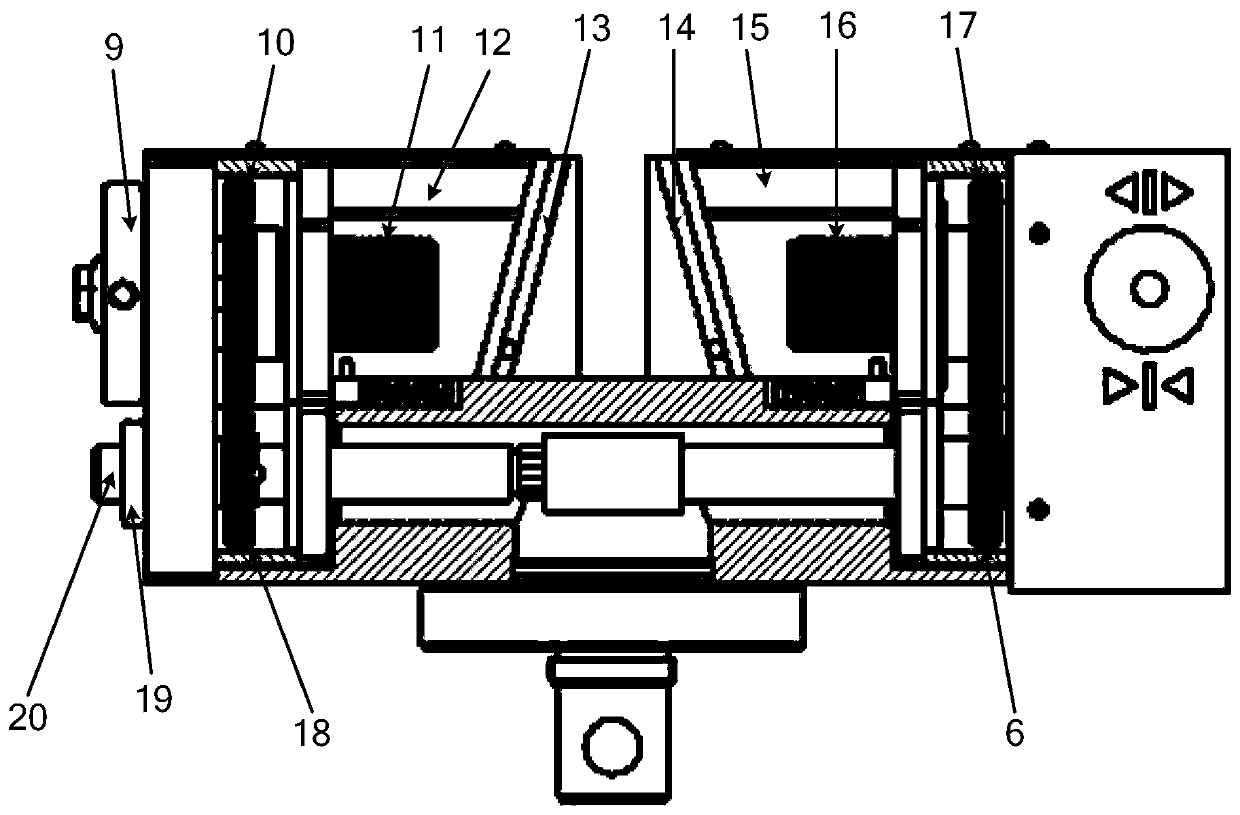
[0040] The core improvement point of the horizontal push wedge clamping device provided by the embodiment of the present inventio...
PUM
Abstract
The invention discloses a horizontal pushing wedged clamping device, and belongs to the field of tester clamps. An execution mechanism of the horizontal pushing wedged clamping device is composed of wedge block bodies and wedge blocks; during testing, the wedge block bodies and a clamp body are stressed; the front end of each wedge block body is a wedged mechanism, so that clamping force can be strengthened as drawing force applied to a sample is strengthened, the sample is not liable to slip, and clamping implemented to the sample is reliable; and meanwhile, operation is simple and convenient, a clamping range is larger than that of a wedged clamp, and in addition, the wedged blocks clamp the sample in a translation manner without any axial additional force. According to the technical scheme, the horizontal pushing wedged clamping device has the advantages that by taking compressed air as a power source, a medium is clean, energy supply is convenient, clamping and loosening are rapid, the test time is short, the working efficiency is high, the labor intensity is low, and the like, and also has various advantages that the initial clamping force is small, the sample can be asymmetrically clamped, and the like. By adopting the device, the tester industry goes up to a new stage, automation of a clamping process can be further realized at the same time, the controllability is strengthened, and a solid foundation is laid for further realizing full automation of material tests.
Description
Technical field [0001] The invention belongs to the technical field of testing machine clamps, and particularly relates to a flat push wedge clamping device for clamping a sample. Background technique [0002] In the material tensile test, the firmness of the clamp on the specimen determines the accuracy of the test data. [0003] In order to hold firmly and reduce the slip between the clamping block and the specimen, the inclined wedge clamping method is widely used on the testing machine, such as figure 1 Shown is a manual wedge clamp, which uses the force generated when the inclined surface moves to clamp the specimen. The diagonal wedge clamp has a small initial clamping force and the clamping force can vary with the tensile force of the specimen The feature of increasing and increasing can effectively avoid the slipping phenomenon of the sample. [0004] However, in the process of clamping the specimen by the wedge-type tensile fixture, an axial thrust is required to be applied...
Claims
Application Information
Patent Timeline
Application Date:The date an application was filed.
Publication Date:The date a patent or application was officially published.
First Publication Date:The earliest publication date of a patent with the same application number.
Issue Date:Publication date of the patent grant document.
PCT Entry Date:The Entry date of PCT National Phase.
Estimated Expiry Date:The statutory expiry date of a patent right according to the Patent Law, and it is the longest term of protection that the patent right can achieve without the termination of the patent right due to other reasons(Term extension factor has been taken into account ).
Invalid Date:Actual expiry date is based on effective date or publication date of legal transaction data of invalid patent.